
Ceiling lamp holder

A lamp stand and pendant lamp technology, which is applied to lighting devices, fixed lighting devices, electric light sources, etc., can solve the problems of expansion and contraction, and it is difficult to adapt to various environments, and achieves the effect of good applicability and strong adjustability.

Inactive Publication Date: 2018-08-28
嘉兴爱劳科斯智能照明有限公司
View PDF4 Cites 2 Cited by
  • Summary
  • Abstract
  • Description
  • Claims
  • Application Information

AI Technical Summary

Problems solved by technology

[0002] The light frame of the traditional chandelier is welded and fixed, it cannot be stretched according to actual needs, and it is difficult to adapt to various environments

Method used


Image

  • Ceiling lamp holder

Examples


Embodiment Construction

[0014] In order to make the technical means, creative features, goals and effects achieved by the present invention easy to understand, the present invention will be further elaborated below in conjunction with illustrations and specific embodiments.

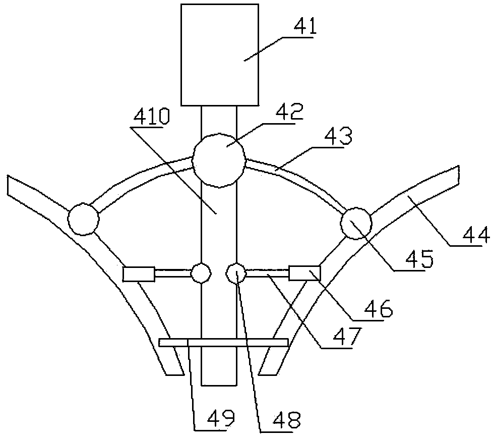
[0015] like figure 1 As shown, a chandelier light stand proposed by the present invention includes a central light pole 410, an inner connecting cylinder 41 screwed to the upper end of the central light pole 410 along the axial direction of the central light pole 410, and a The first integrated ball 42 screwed on the central light pole 410 and on the lower side of the inner connecting cylinder 41, the second fixed ball 48 screwed on the side wall of the central light pole 410, along the The radial direction of the second fixed ball 48 is screwed on the inner tightening rod 47 on the second fixed ball 48, and the inner tightening rod 47 sleeved on the inner tightening rod 47 is far away from the second fixed ball 48. The telesco...


PUM


Abstract

The invention relates to the technical field of lamps, and provides a ceiling lamp holder. The ceiling lamp holder comprises a center lamp pole, an inner connecting cylinder, a first integrated ball,second integrated balls, inner jacking rods, telescopic adjusting cylinders, a transverse connecting rod, outer lamp poles, first fixing balls and stretching adjusting rods, wherein the inner connecting cylinder is in threaded connection with the upper end of the central lamp pole in the axial direction of the central lamp pole, the first integrated ball is in threaded connection with the centrallamp pole and located on the lower side of the inner connecting cylinder, the second fixing balls are connected to the side wall of the central lamp pole in a screwed mode, the inner jacking rods arein threaded connection with the second fixing balls in the radial directions of the second fixing balls, the telescopic adjusting cylinders sleeve one ends, far away from the second fixing balls, of the inner jacking rods, the transverse connecting rod is arranged at the lower end of the central lamp pole in a penetrating mode, the outer lamp poles are connected to the end of the transverse connecting rod in a clamped mode, the first fixing balls are arranged on the side walls of the outer lamp poles in a screwed mode, the stretching adjusting rods are arranged in the first integrated ball inthe radial direction of the first integrated ball in a penetrating mode, and the end portions of the stretching adjusting rods are connected onto the first fixing balls in a clamped mode.

Description

technical field [0001] The invention relates to the technical field of lamps, in particular to a lamp holder for a chandelier. Background technique [0002] The light frame of the traditional chandelier is welded and fixed, and cannot be stretched according to actual needs, so it is difficult to adapt to various environments. Therefore, it is necessary for us to improve such a structure to overcome the above-mentioned defects. Contents of the invention [0003] The object of the present invention is to provide a chandelier light frame. [0004] The technical scheme that the present invention adopts for solving its technical problem is: [0005] A chandelier light stand, comprising a central light pole, an inner connecting cylinder screwed to the upper end of the central light pole along the axial direction of the central light pole, screwed to the central light pole through threads, and The first integrated ball on the lower side of the inner connecting cylinder, the se...

Claims


Application Information

Patent Timeline
IPC IPC(8): F21S8/06F21V21/22
CPCF21S8/063F21V21/22
Inventor 叶仁良
Owner 嘉兴爱劳科斯智能照明有限公司
Features
  • Generate Ideas
  • Intellectual Property
  • Life Sciences
  • Materials
  • Tech Scout
  • Unparalleled Data Quality
  • Higher Quality Content
  • 60% Fewer Hallucinations
Learn More