
Hoisting device and hoisting method applied to high-altitude hoisting of umbrella-shaped column light component

A light-weight component and hoisting device technology, applied in building components, special structures, walking mechanisms, etc., can solve the problems of limited construction operation space, high cost of construction equipment, poor mobility and other problems, achieve fast production, improve construction efficiency, strong The effect of adjustability

Active Publication Date: 2020-07-17
CHINA CONSTR EIGHT ENG DIV CORP LTD
View PDF5 Cites 0 Cited by
  • Summary
  • Abstract
  • Description
  • Claims
  • Application Information

AI Technical Summary

Problems solved by technology

[0004] In view of the above situation, the present invention provides a hoisting device and hoisting method applied to the high-altitude hoisting of light-duty umbrella-shaped columns, which solves the problem of easy collision with components during the hoisting process of light-weight enclosure components in the construction of existing umbrella-shaped columns, and the construction operation space is limited. Constraints and defects of high cost of construction equipment, low turnover efficiency, and poor mobility

Method used


Image

  • Hoisting device and hoisting method applied to high-altitude hoisting of umbrella-shaped column light component
  • Hoisting device and hoisting method applied to high-altitude hoisting of umbrella-shaped column light component
  • Hoisting device and hoisting method applied to high-altitude hoisting of umbrella-shaped column light component

Examples


Embodiment Construction

[0043] In order to facilitate the understanding of the present invention, the following will be described in conjunction with the accompanying drawings and embodiments.

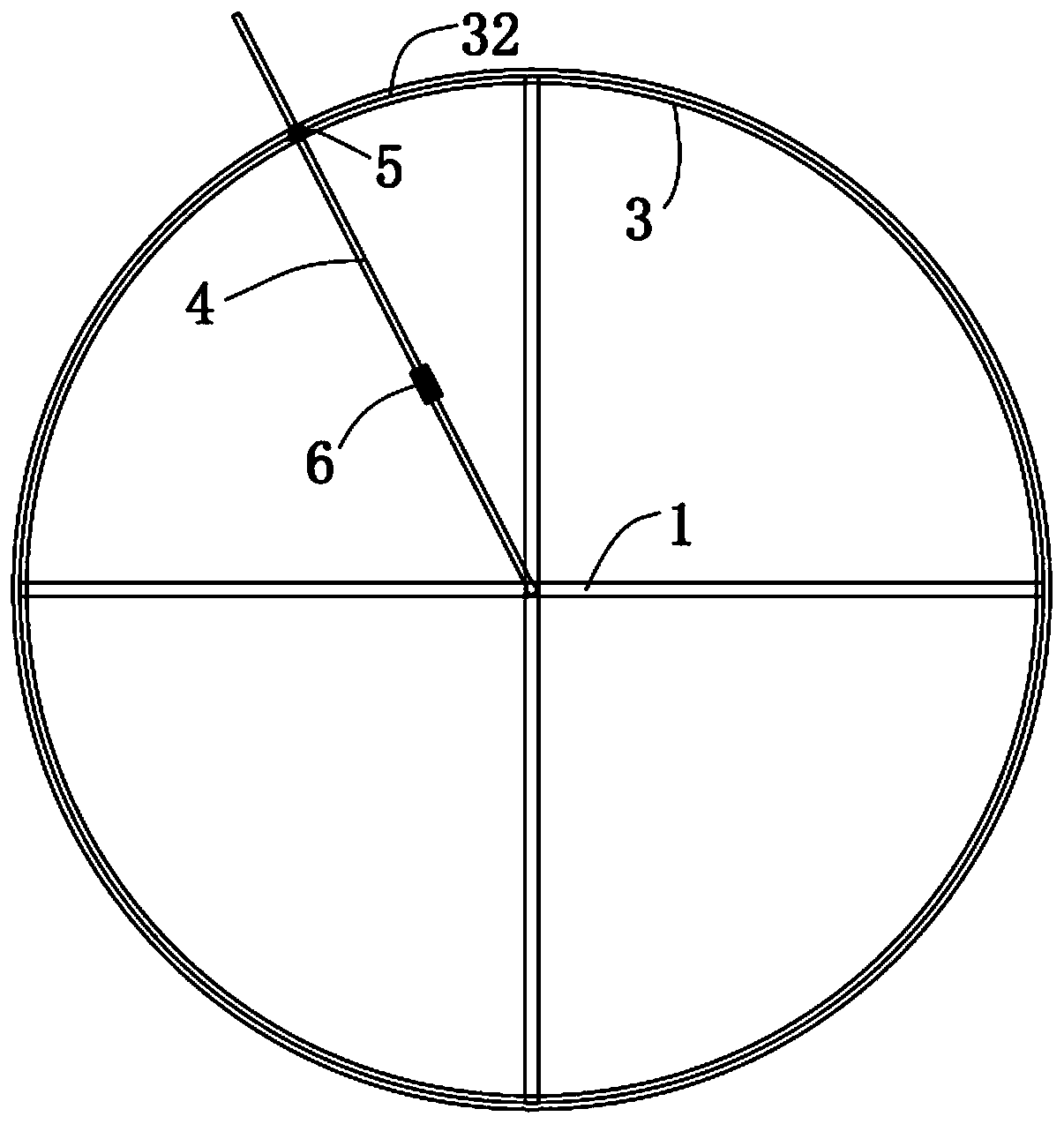
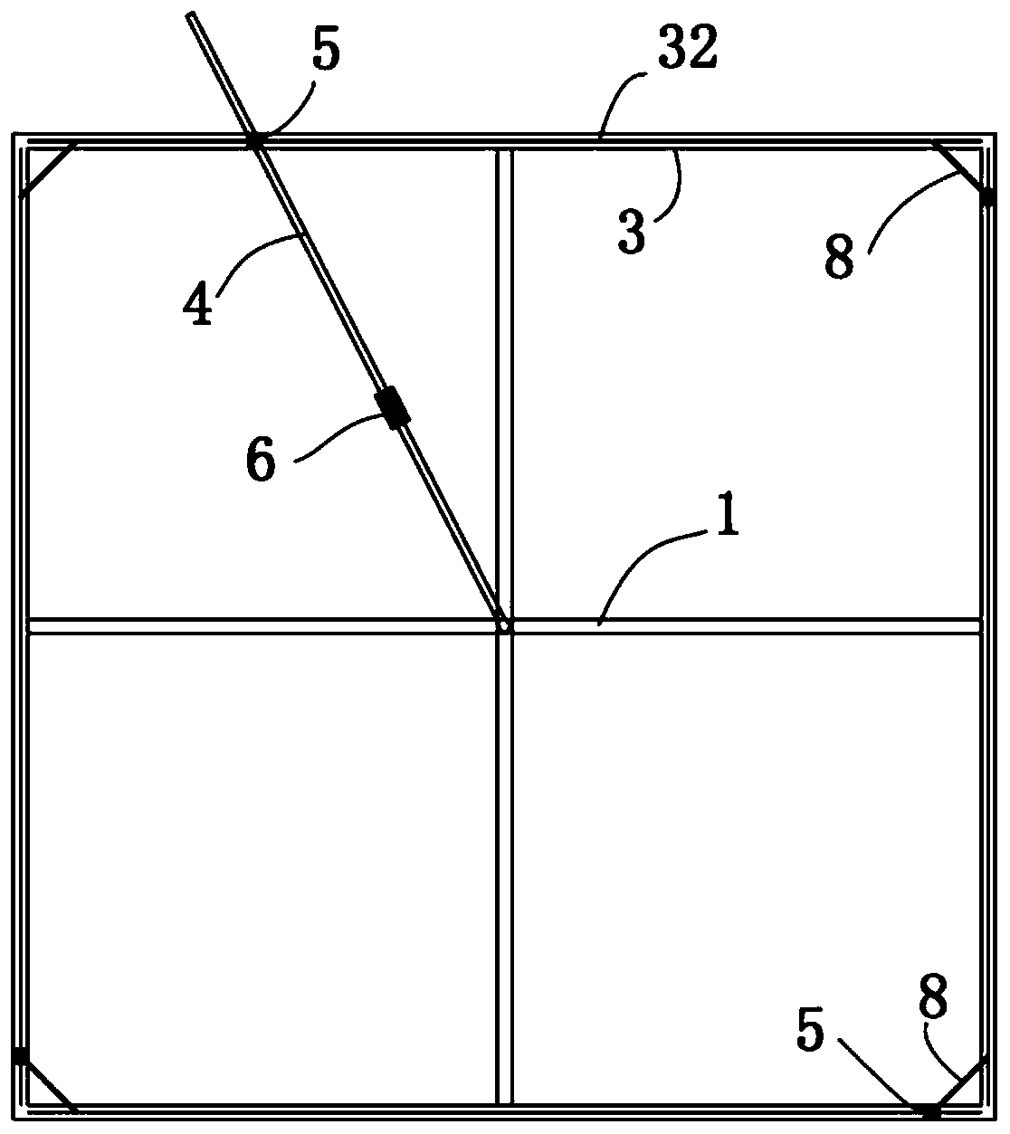
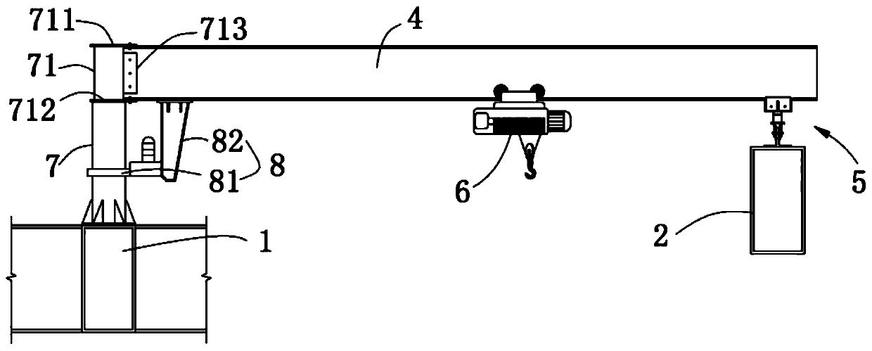
[0044] see Figure 1 to Figure 3 , the present invention provides a hoisting device applied to the high-altitude hoisting of umbrella-shaped light-weight components. Column edge beam 2; described hoisting device comprises track 3, crane beam 4, slide assembly 5 and hoisting part 6, carries out the hoisting of the required light member of umbrella-shaped column construction by above-mentioned device being installed on the top of umbrella-shaped column, so The range of motion of the hoisting device is small, and it is not easy to collide with other structures during the hoisting of light components. Compared with the hoisting equipment in the prior art, the application uses the crane beam 4, the track 3, the sliding assembly 5 and the lifting parts The hoisting system composed of 6 has simple structure, conven...


PUM


Abstract

The invention provides a hoisting device and a hoisting method applied to high-altitude hoisting of an umbrella-shaped column light component. An umbrella-shaped column comprises an umbrella-shaped column main beam, and umbrella-shaped column side beams are horizontally arranged around the periphery of the umbrella-shaped column main beam in a surrounding mode. The hoisting device comprises rails,crane beams and hoisting pieces, wherein the rails are laid on the umbrella-shaped column side beams; the first ends of the crane beams are horizontally and rotatably connected to the umbrella-shapedcolumn main beam, sliding assemblies which slide in the extending directions of the crane beams are arranged at the bottoms of the crane beams, and the sliding assemblies are arranged on the rails ina sliding mode; and the hoisting pieces are arranged on the crane beams in a sliding mode and located between the sliding assemblies and the first ends of the crane beams. The hoisting device is arranged in the space of the umbrella-shaped column main beam and the umbrella-shaped column side beams, the problems of collision between a suspension arm of an automobile crane and the component and thelike are avoided, construction can be carried out on a plurality of umbrella-shaped columns at the same time, the efficiency is high, the self weight is light, and disassembly, assembly and turnoveruse are convenient.

Description

technical field [0001] The invention relates to the technical field of building construction, in particular to a hoisting device and a hoisting method applied to high-altitude hoisting of umbrella-shaped column light components. Background technique [0002] With the improvement of aesthetic requirements for urban buildings, umbrella-shaped column steel structure roof systems are increasingly appearing in people's field of vision, such as the Sunshine Valley of Shanghai World Expo, Tianjin Binhai Cultural Center, Tianjin National Convention and Exhibition Central Hall, etc. The shape of the umbrella-shaped column is spectacular and smooth, but light enclosure components such as louvers and purlins are densely arranged, and the on-site installation workload is heavy; the umbrella column is often more than 30 meters high, and the operating radius of the construction machinery is required to be large enough; the inverted pyramid or inverted cone The shape is easy to collide wit...

Claims


Application Information

Patent Timeline
IPC IPC(8): B66C19/00B66C9/04B66C9/08B66C9/18B66C7/08B66C7/12E04B1/34
CPCB66C7/08B66C7/12B66C9/04B66C9/08B66C9/18B66C19/00E04B1/3416
Inventor 吴旦翔朱雪亮林南昌
Owner CHINA CONSTR EIGHT ENG DIV CORP LTD
Learn More