Ball head assembly for attaching optical and/or electronic equipment to a stand
What is AI technical title?
AI technical title is built by Patsnap AI team. It summarizes the technical point description of the patent document.
A technology of electronic equipment and spherical head, which is applied in the direction of machines/brackets, optics, mechanical equipment, etc., and can solve problems such as inability to ensure the positioning of the reference plane
Active Publication Date: 2021-02-05
巴拉兹卡门 +1
View PDF2 Cites 0 Cited by
Summary
Abstract
Description
Claims
Application Information
AI Technical Summary
This helps you quickly interpret patents by identifying the three key elements:
Problems solved by technology
Method used
Benefits of technology
Problems solved by technology
In this "reverse" design, the positioning of the reference plane cannot be ensured, i.e. the reduction of the degrees of freedom from three to two is carried out in such a way that the horizontal line can fit onto the support reference plane in each adjustment position
Method used
Image
Click on the blue label to locate the original text in one second.
Reading with bidirectional positioning of images and text.
Examples
Embodiment Construction
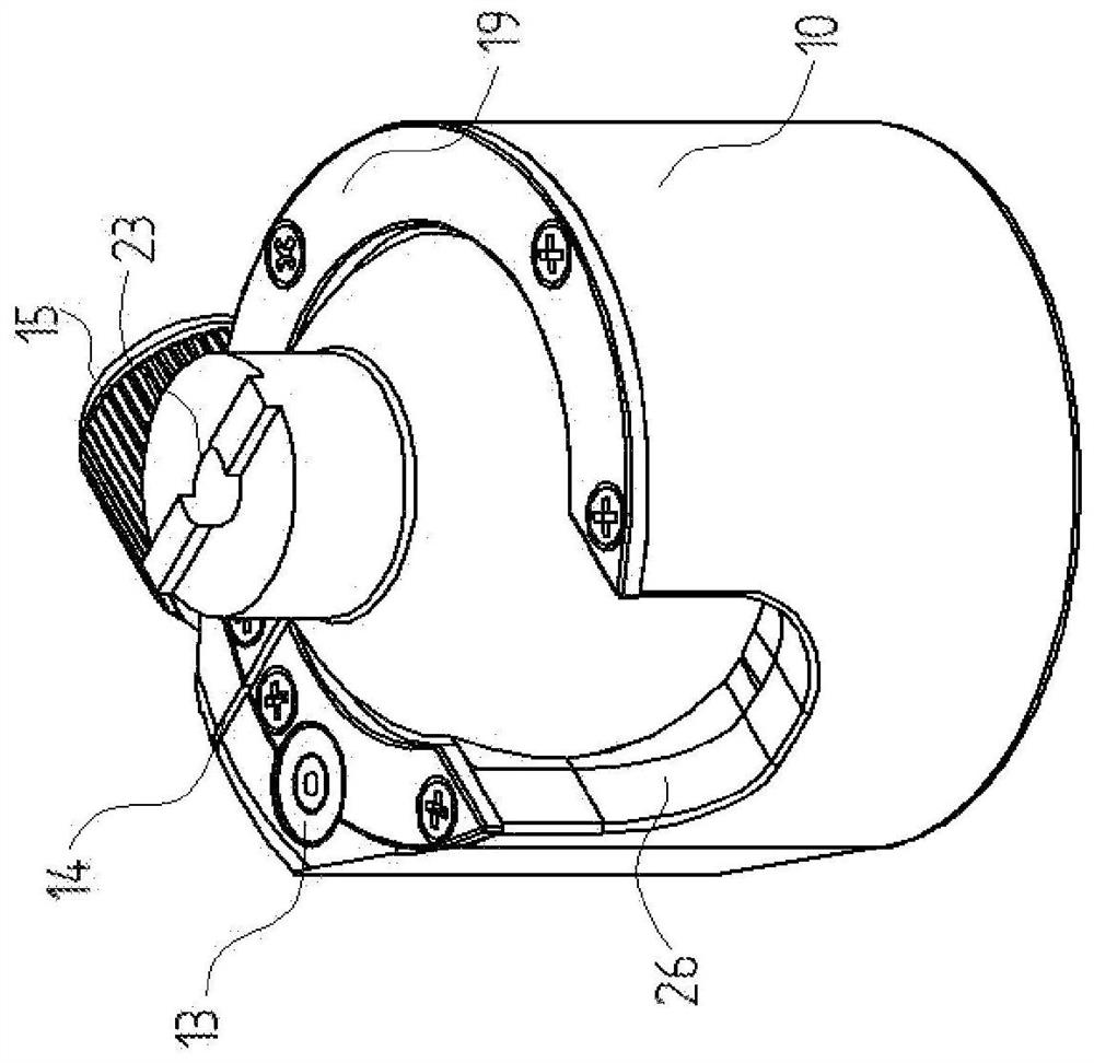
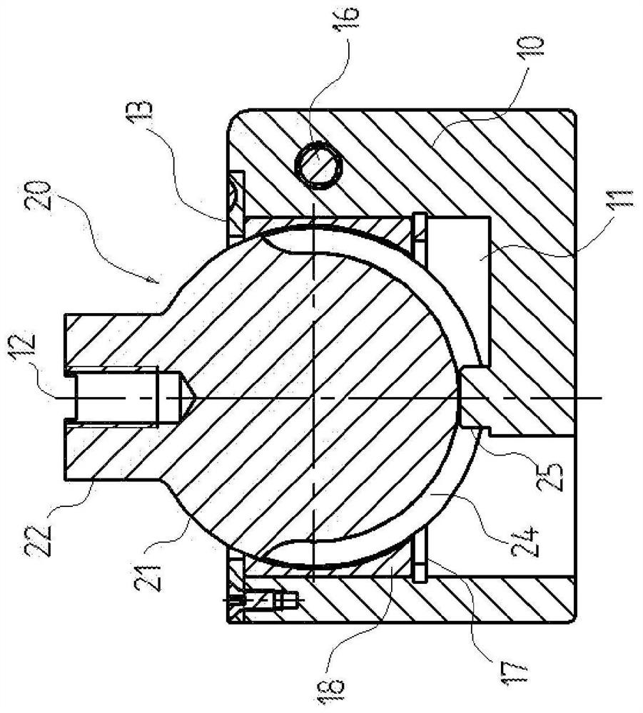
[0048] figure 1 and figure 2 A first embodiment of a ball head according to the invention is shown, comprising an upright housing 10 with a vertical axis and inside said upright housing a cylindrical chamber 11 is provided, as figure 2 As shown in the sectional view of , and the axis 12 of the chamber 11 does not necessarily coincide with the axis of the housing 10 . The reason for this is that, in a preferred embodiment, the wall thickness of the housing 10 can be increased within a given angular range, and a leveling bubble 13 that facilitates labeling can be provided on the upper part of the thicker portion. . figure 1 and 2 shows such a design. The wall of the housing 10 preferably in the middle of the thicker part comprises a slot 14 extending parallel to the axis 12 and which can be compressed by means of an adjusting screw having an adjusting head 15 with large knurling and in figure 2 A threaded rod 16 can be seen in the sectional view, said threaded rod 16 en...
PUM
Abstract
A ball head assembly for attaching an optical and / or electronic device to a mount having at least two degrees of freedom of adjustability is disclosed, the assembly having a first portion and a second portion, the first portion being releasably connectable To the bracket, the second part is provided with a support element for releasably connecting the held device, one of the two parts being a spherical head (20, 100) having an at least partially spherical body ( 21, 99), the other part includes a chamber formed as a spherical section that at least partially surrounds the spherical head (20, 100) and cooperates with the spherical head, the spherical head assembly also includes an adjustment device, the adjustment device is used Upon coupling the two parts together and releasing the coupling, the retained device is adjusted to a horizontal or nearly horizontal position in the initial position intended for use. In the second part there is provided a groove (24, 108) having a vertical center plane and extending along the largest diameter of the spherical section, provided on the first part at a position corresponding to the vertical diameter of the spherical section There are circular symmetrical columns (25, 103) which can be fitted in the grooves (24, 108), in the fitted position the columns (25, 103) allow and guide the two parts along said grooves (24 , 108) is displaced, and the column (25, 103) allows the two coupled spherical fit sections to rotate around the vertical axis of the column (25, 103) at each adjustment position, and the adjustment device is arranged at On the one of the two parts with the spherical cavity, the adjusting means presses the cavity to the spherical body (21, 99) when the positions of the two parts are fixed.
Description
technical field [0001] The present invention relates to a ball head assembly for attaching an optical and / or electronic device to a mount, the ball head assembly having at least two degrees of freedom of adjustability, wherein the ball head assembly has features connectable to the mount and A first part is releasably secured to the bracket and a second part is provided with support elements for releasably attaching and holding said device. The spherical head assembly according to the invention can be used primarily for holding and positioning of optical equipment such as cameras, video and film recorders and projectors and which are designed to be held on a type of stand, typically on a tripod superior. Background technique [0002] More precisely, one of the aforementioned two parts of the spherical head assembly consists of a spherical head with a spherical body at least partially formed as a sphere, and the other part comprises a chamber designed as a spherical cross-sec...
Claims
Application Information
Patent Timeline
Application Date:The date an application was filed.
Publication Date:The date a patent or application was officially published.
First Publication Date:The earliest publication date of a patent with the same application number.
Issue Date:Publication date of the patent grant document.
PCT Entry Date:The Entry date of PCT National Phase.
Estimated Expiry Date:The statutory expiry date of a patent right according to the Patent Law, and it is the longest term of protection that the patent right can achieve without the termination of the patent right due to other reasons(Term extension factor has been taken into account ).
Invalid Date:Actual expiry date is based on effective date or publication date of legal transaction data of invalid patent.

