
Drill rod displacement triggering mechanism

A trigger mechanism and chisel technology, which is applied to earth movers/shovels, mechanically driven excavators/dredgers, roads, etc., can solve problems such as inability to release knocking kinetic energy, damage to chisel rods, and increased equipment operating costs

Active Publication Date: 2018-09-04
HAIMEN THE YELLOW SEA ENTREPRENEURSHIP PARK SERVICE CO LTD
View PDF6 Cites 1 Cited by
  • Summary
  • Abstract
  • Description
  • Claims
  • Application Information

AI Technical Summary

Problems solved by technology

[0003] At present, the breaker has various drive modes such as hydraulic drive, nitrogen drive, nitrogen and hydraulic drive, gravity drive, etc. Each drive mode is achieved by hitting the drill rod at high speed so that the drill rod has a large kinetic energy in an instant to achieve crushing. The effect of the object; when the chisel is hit, the huge kinetic energy is released by breaking the object, but the chisel is often separated from the object during work, and the beating is still in progress at this time, and the huge beating kinetic energy cannot be released. Hitting will cause great damage to the drill rod, resulting in increased equipment operating costs

Method used


Image

  • Drill rod displacement triggering mechanism
  • Drill rod displacement triggering mechanism
  • Drill rod displacement triggering mechanism

Examples


Embodiment Construction

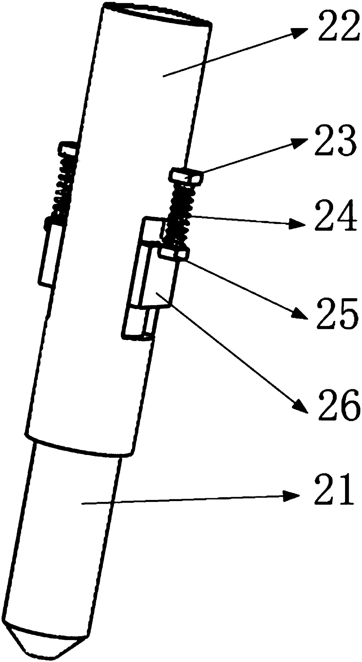
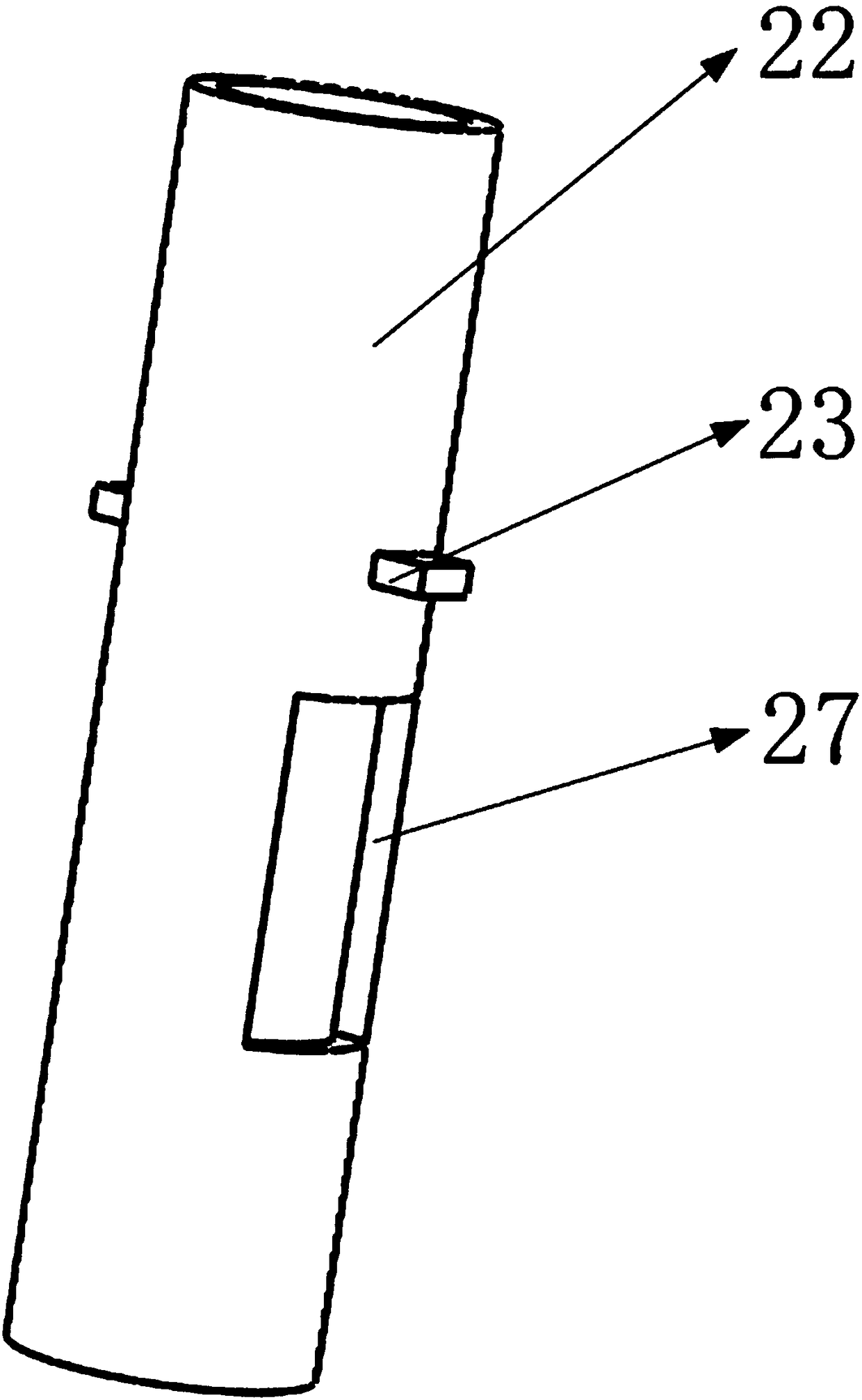
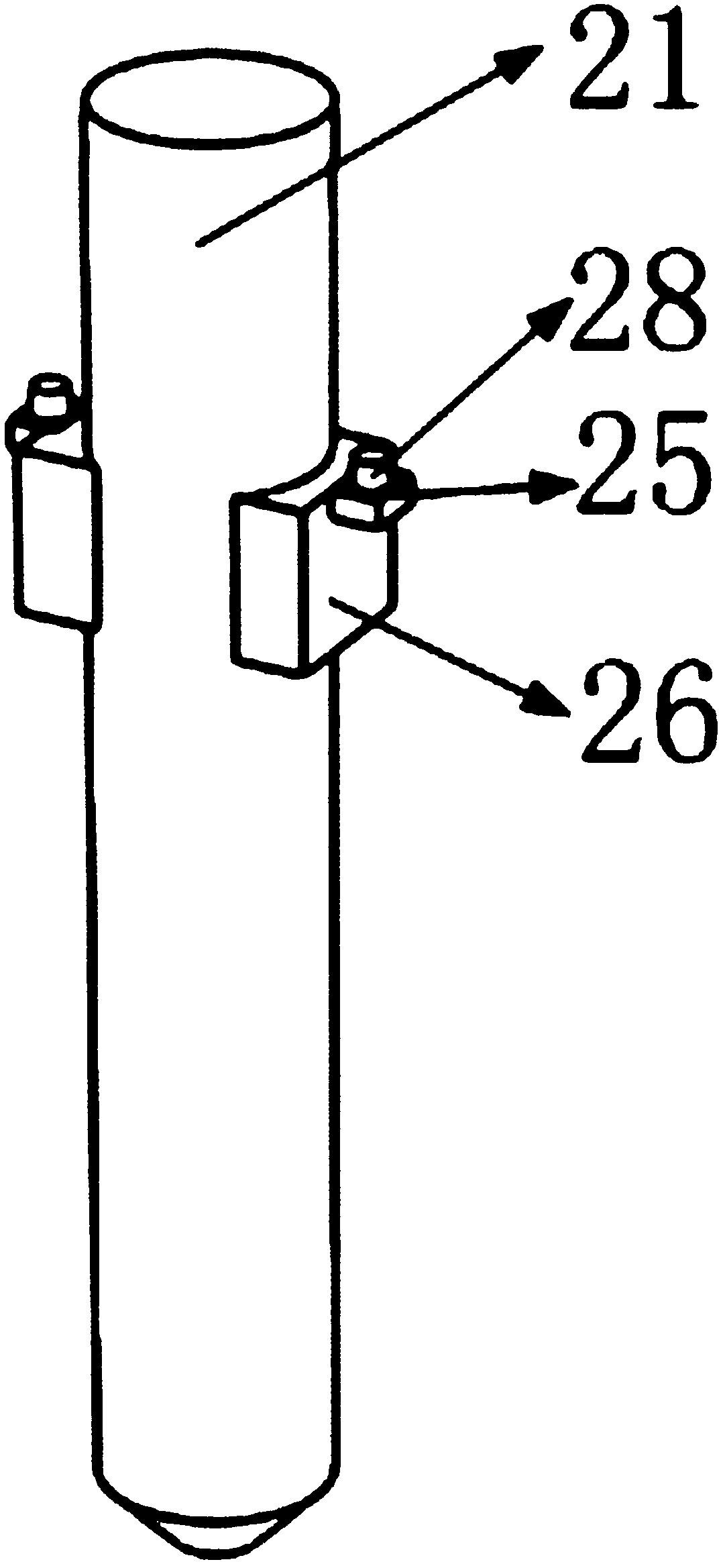
[0022] like Figure 4 As shown, it includes a drive slider, a limit block, a guide rail, a first support plate, an amplitude valve body, a first valve block, a hydraulic hole, a second valve block, a third valve block, a fourth valve block, and a second support Plate, drive chute, valve body chute, valve body shell, third support plate, valve body spring, drill rod, drill rod sleeve, first drill rod spring support, drill rod spring, second drill rod spring support, drill rod Rod guide block, drill rod sleeve sliding hole, spring pin, such as figure 2 As shown, there is a drill rod sleeve sliding hole in the lower part of the drill rod sleeve and runs through the whole drill rod sleeve, and the two first drill rod spring supports are symmetrically installed on the drill rod sleeve and are located on the upper side of the drill rod sleeve sliding hole ,like image 3 As shown in the figure, two drill rod guide blocks are symmetrically installed in the middle of the drill rod, ...


PUM


Abstract

The invention discloses a drill rod displacement triggering mechanism. The drill rod displacement triggering mechanism comprises a driving sliding block, a limiting block, an amplitude valve body, a hydraulic hole, a valve body shell, a valve body spring, a drill rod, a drill rod sleeve and a drill rod spring; the drill rod is mounted in the drill rod sleeve through sliding fit of a drill rod guiding block and a drill rod sleeve sliding hole, the drill rod spring is mounted on the guiding block, and the drill rod spring plays a role of resetting the drill rod when the drill rod knocks and works in a reciprocating mode; and the valve body shell is mounted on the drill rod sleeve through a first supporting plate, a second supporting plate and a third supporting plate, the amplitude valve body is mounted on the valve body shell, and the valve body spring is mounted between the amplitude valve body and the third supporting plate. In the drill rod displacement triggering mechanism, only after the drill rod applies certain force to an object, the drill rod contracts inwards, an oil circuit can be opened to start a knocking mechanism, as long as the drill rod gets away from the object, the knocking mechanism immediately stops knocking, the phenomenon of idling knocking of the drill rod is prevented, the service life of the drill rod is prolonged, and the good using effect is achieved.

Description

[0001] This application is a divisional application for a patent with an application number of 2016103778339, an application date of May 31, 2016, and an invention and creation titled "A drill rod displacement trigger mechanism for a breaker". technical field [0002] The invention belongs to the technical field of breakers, and in particular relates to a drill rod displacement trigger mechanism for breakers. Background technique [0003] At present, the breaker has a variety of driving modes, such as hydraulic drive, nitrogen drive, nitrogen and hydraulic hybrid drive, and gravity drive. Each drive method is to achieve crushing by hitting the drill rod at a high speed, so that the drill rod has a large kinetic energy in an instant. The effect of the object; when the drill rod is hit, the huge kinetic energy is released by breaking the object, but the drill rod is often separated from the object during work, and the beating is still in progress at this time, and the huge kine...

Claims


Application Information

Patent Timeline
Patent Type & Authority Applications(China)
IPC IPC(8): E01C23/12E02F3/96
CPCE01C23/124E02F3/966
Inventor 不公告发明人
Owner HAIMEN THE YELLOW SEA ENTREPRENEURSHIP PARK SERVICE CO LTD
Learn More