Turning device

A technology of rotating devices and motion slots, which is applied in the direction of lighting devices, lighting auxiliary devices, lighting device components, etc., and can solve problems such as small deflection angles and inflexible rotation

Active Publication Date: 2020-01-03
东莞市闻誉实业有限公司
View PDF11 Cites 0 Cited by
  • Summary
  • Abstract
  • Description
  • Claims
  • Application Information

AI Technical Summary

Problems solved by technology

However, the rotation of the traditional rotating structure is relatively inflexible, and the deflection angle is small

Method used


Image

  • Turning device
  • Turning device
  • Turning device

Examples


Embodiment Construction

[0020] In order to make the purpose, technical solution and advantages of the present invention clearer, the present invention will be further described in detail with reference to the accompanying drawings by taking a large provincial power grid as an example. It should be understood that the specific embodiments described here are only used to explain the present invention, not to limit the present invention.

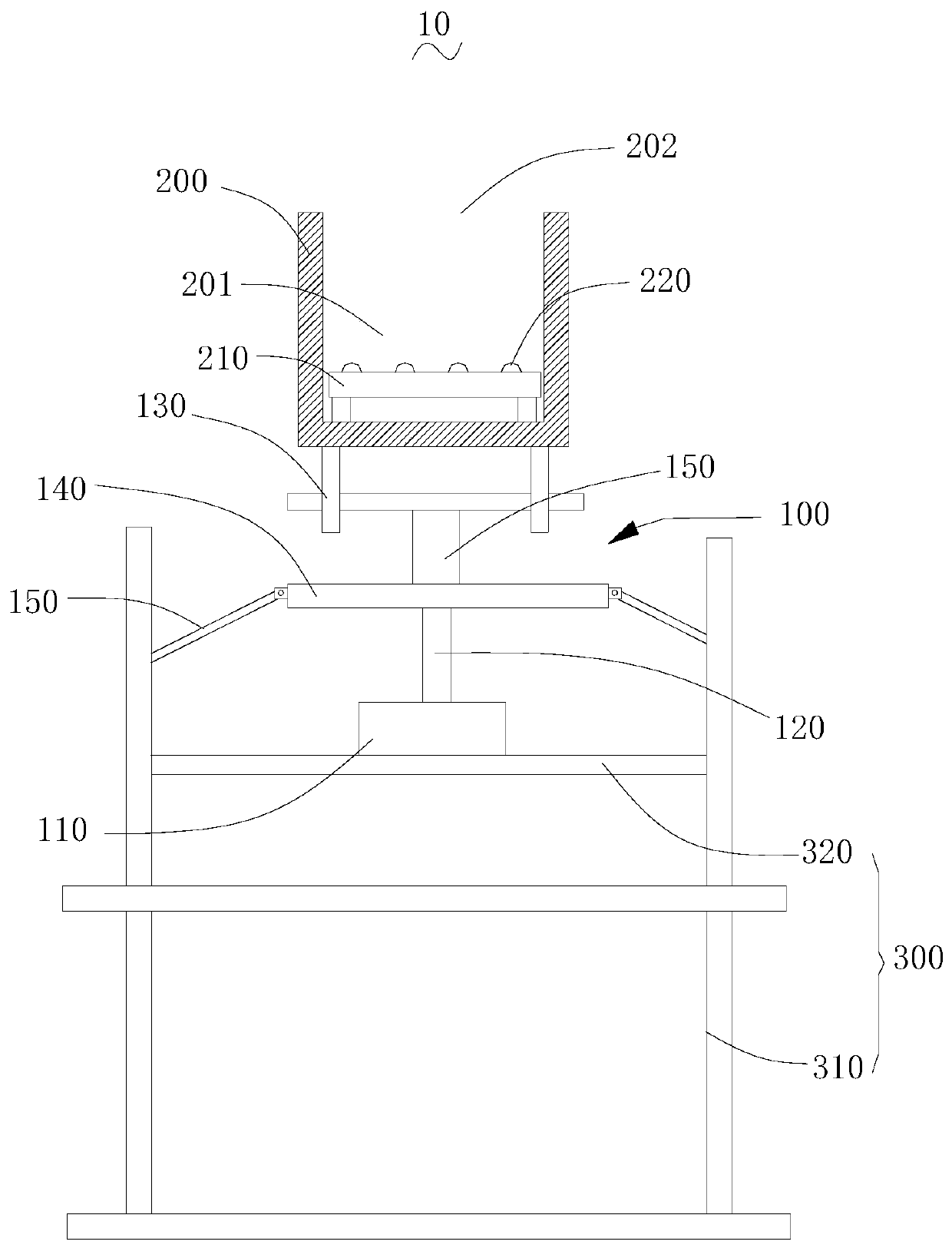
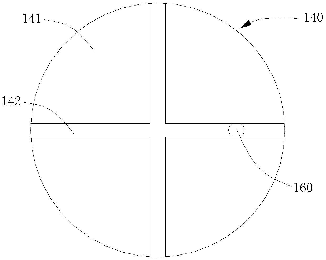
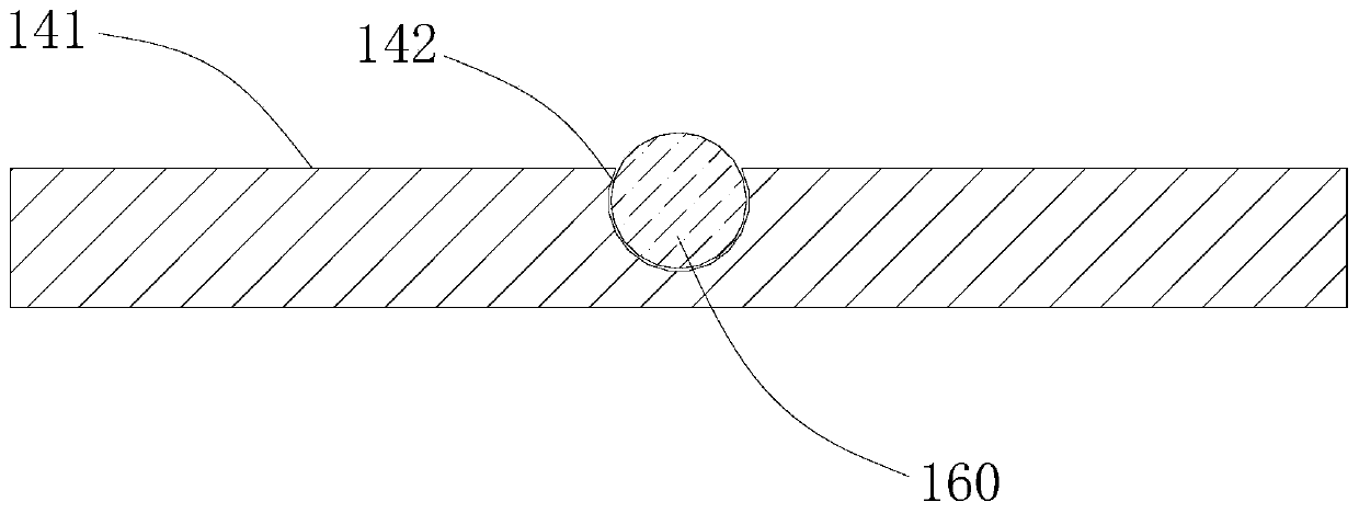
[0021] For example, a rotating device includes: a driver, a drive shaft, a multi-directional connector, a connecting shaft and a movable frame, the driver is drivingly connected to the drive shaft, a ball is provided at one end of the drive shaft, and the multi-directional The connector has a moving surface, and at least one moving groove is opened on the moving surface, and the moving grooves are interlaced and communicated with each other. The balls are rolled in each moving groove, and the connecting shaft and the The side of the multidirectional connector facing a...


PUM


Abstract

The invention relates to a rotary device. The rotary device comprises a driver, a drive shaft, a multi-direction connector, a connecting shaft and a movable frame, wherein the driver is in driving connection with the drive shaft; a rolling ball is arranged at one end of the drive shaft; the multi-direction connector is provided with a motion surface; at least one motion slot is formed in the motion surface; the rolling ball is arranged in each motion slot in a rolling mode; the connecting shaft is movably connected with one surface, away from the motion surface, of the multi-direction connector; and the connecting shaft is movably connected with the movable frame. The drive shaft moves along the drive axis, the rolling ball axially moves along the drive shaft under the action of the driveshaft, and moves along the motion slot, and the rolling ball generates pushing force on the multi-direction connector, so that the multi-direction connector generates shift or rotation; the multi-direction connector drives the connecting shaft to move, so that the connecting shaft generates displacement; the connecting shaft drives the movable frame to move, so that drive on rotation of the movable frame is realized, and therefore, deflection of the movable frame is more flexible, and the rotation angle is greater.

Description

technical field [0001] The invention relates to the technical field of rotation drive, in particular to a rotation device. Background technique [0002] The traditional rotation structure is realized through a three-axis connection structure, and the driver drives the object to rotate in the radial direction of the three axes, thereby realizing angle adjustment. However, the rotation of the traditional rotating structure is relatively inflexible, and the deflection angle is relatively small. Contents of the invention [0003] Based on this, it is necessary to provide a rotating device. [0004] A projection lamp, comprising: a driver, a driving shaft, a multi-directional connector, a connecting shaft and a movable frame, the driver is drivingly connected to the driving shaft, one end of the driving shaft is provided with a ball, and the multi-directional connecting device There is a moving surface, and at least one moving groove is provided on the moving surface, and the...

Claims


Application Information

Patent Timeline
Patent Type & Authority Patents(China)
IPC IPC(8): F21V21/30
CPCF21V21/30
Inventor 叶伟炳
Owner 东莞市闻誉实业有限公司
Why Eureka
Try Eureka