Hydraulic drive device

A driving device, hydraulic technology, applied in the direction of machines/engines, rotary piston engines, rotary or oscillating piston engines, etc.

Active Publication Date: 2011-08-31
ZHANGJIAGANG SHENGMEIYI MACHINERY
View PDF10 Cites 0 Cited by
  • Summary
  • Abstract
  • Description
  • Claims
  • Application Information

AI Technical Summary

Problems solved by technology

The disadvantage is that after using the cylinder as the power source, the fit and connection of various parts need to be very precise. Once a link is worn or a slight angle occurs, the cylinder will stop working, and the compressed air on the ship is very unstable. Therefore, this driving method It is rarely used; the second power source is the motor, which drives the gears to achieve non-stop slow rotation. The disadvantage is that it needs to use 220V high-voltage electricity, and the safety factor is relatively low. In addition, the motor drive will not be damaged due to wear or tear. A certain link is deformed and stopped, so the reliability in the working process is relatively low

Method used


Image

  • Hydraulic drive device
  • Hydraulic drive device
  • Hydraulic drive device

Examples


Embodiment Construction

[0027] The present invention will be described in further detail below through specific examples.

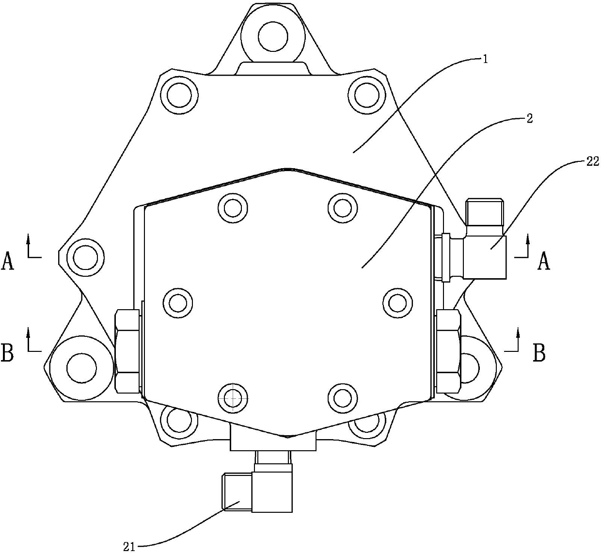
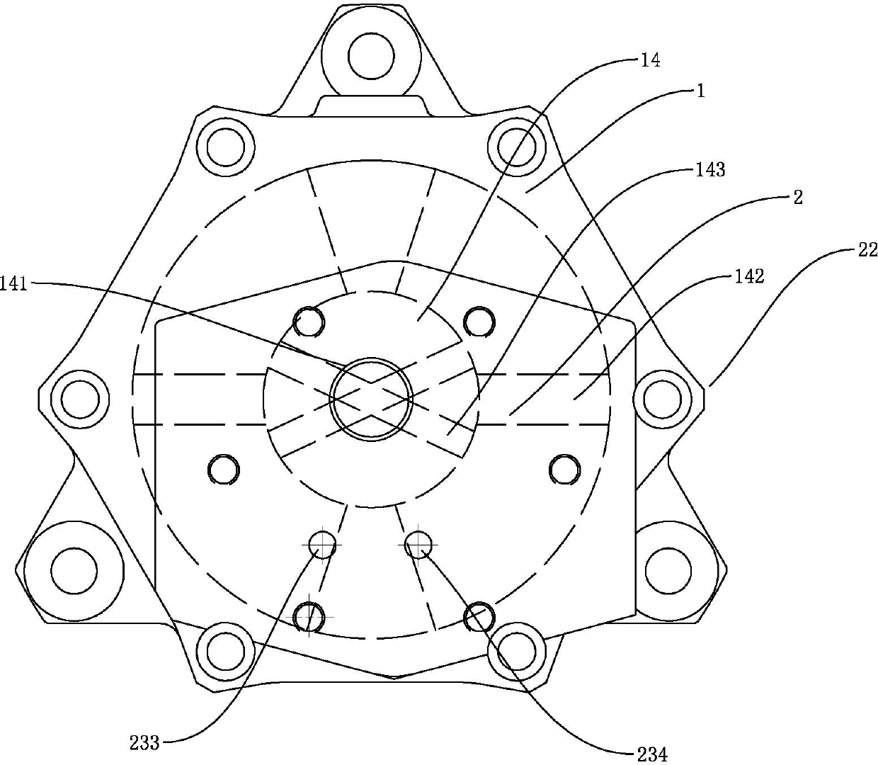
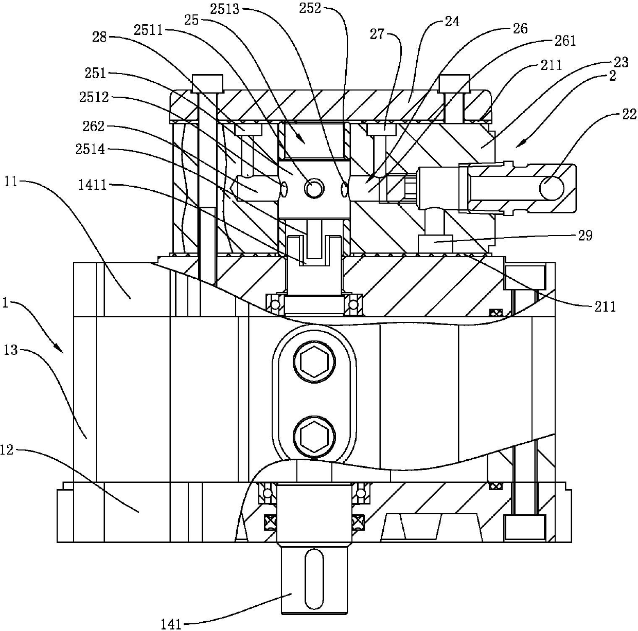
[0028] A hydraulic drive such as Figure 1 to Figure 13 As shown, it includes a hydraulic motor 1, the hydraulic motor 1 includes a stator 13 and a rotor 14 arranged in the stator 13, the upper end and the lower end of the stator 13 respectively fix the motor upper cover 11 and the motor lower cover 12, the stator 13 The rotor 14 is fixed between the motor upper cover 11 and the motor lower cover 12 by bolts, and the rotor 14 is rotatably installed in the stator 13 through a bearing and is sealed and matched by a sealing ring. The stator 13 is provided with two symmetrical liquid baffles 135, and the rotor 14 is provided with two symmetrical vanes 142. The two liquid baffles 135 and the two vanes 142 divide the cavity in the stator 13 into four liquid storage chambers. ,Such as Figure 4 As shown, they are respectively called the first liquid storage chamber 131, the second li...


PUM


Abstract

The invention discloses a hydraulic drive device comprising a hydraulic motor, as well as a three-position two-way reversing valve fixed on the hydraulic motor, wherein the hydraulic motor comprises a stator and a rotor; the three-position two-way reversing valve comprises a valve body; the valve body is internally provided with a valve chest and a valve rod; the valve body is provided with a first driving liquid path, a second driving liquid path, a return liquid path, an inlet liquid path and an outlet liquid path; the return liquid path is close to the second driving liquid path and communicated with the outlet liquid path; the inlet liquid path is communicated with the valve chest; the outer periphery of the valve rod is provided with three annular convex parts; two adjacent annular convex parts form an inlet liquid groove and a return liquid groove in between; the valve rod is provided with a return liquid channel that stretches axially and communicates the return liquid path with the first driving liquid path when the valve rod slides to another station; and the valve body is internally rotatably provided with a reversing device that is linked with the rotor and enables the valve rod to slide back and forth along the valve chest to reverse the liquid paths back and forth. The hydraulic drive device is strong in safety and reliability and simple and convenient in operation.

Description

technical field [0001] The invention relates to a driving device, in particular to a hydraulic driving device used on ships. Background technique [0002] The first power source for the fully automatic backwashing filter installed on the ship is the cylinder, and the intermittent rotation is realized by the conversion of the ratchet mechanism through the reciprocating linear motion of the cylinder. The disadvantage is that after using the cylinder as the power source, the fit and connection of various parts need to be very precise. Once a link is worn or a slight angle occurs, the cylinder will stop working, and the compressed air on the ship is very unstable. Therefore, this driving method It is rarely used; the second power source is the motor, which drives the gears to achieve non-stop slow rotation. The disadvantage is that it needs to use 220V high-voltage electricity, and the safety factor is relatively low. In addition, the motor drive will not be damaged due to wear ...

Claims


Application Information

Patent Timeline
Patent Type & Authority Applications(China)
IPC IPC(8): F03C2/00
Inventor 黄圣达王美芬惠炳洪宋春梅
Owner ZHANGJIAGANG SHENGMEIYI MACHINERY
Why Eureka
Try Eureka