Full-automatic optical fiber cutting knife

A cutting knife, fully automatic technology, applied in the coupling of optical waveguide, metal processing, etc., can solve the problem of not having a fully automatic optical fiber cutting knife

Active Publication Date: 2013-03-20
INNO INSTR (CHINA) INC
View PDF7 Cites 17 Cited by
  • Summary
  • Abstract
  • Description
  • Claims
  • Application Information

AI Technical Summary

Problems solved by technology

[0012] The purpose of the present invention is to provide a fully automatic optical fiber cutter

Method used


Image

  • Full-automatic optical fiber cutting knife
  • Full-automatic optical fiber cutting knife
  • Full-automatic optical fiber cutting knife

Examples


Embodiment Construction

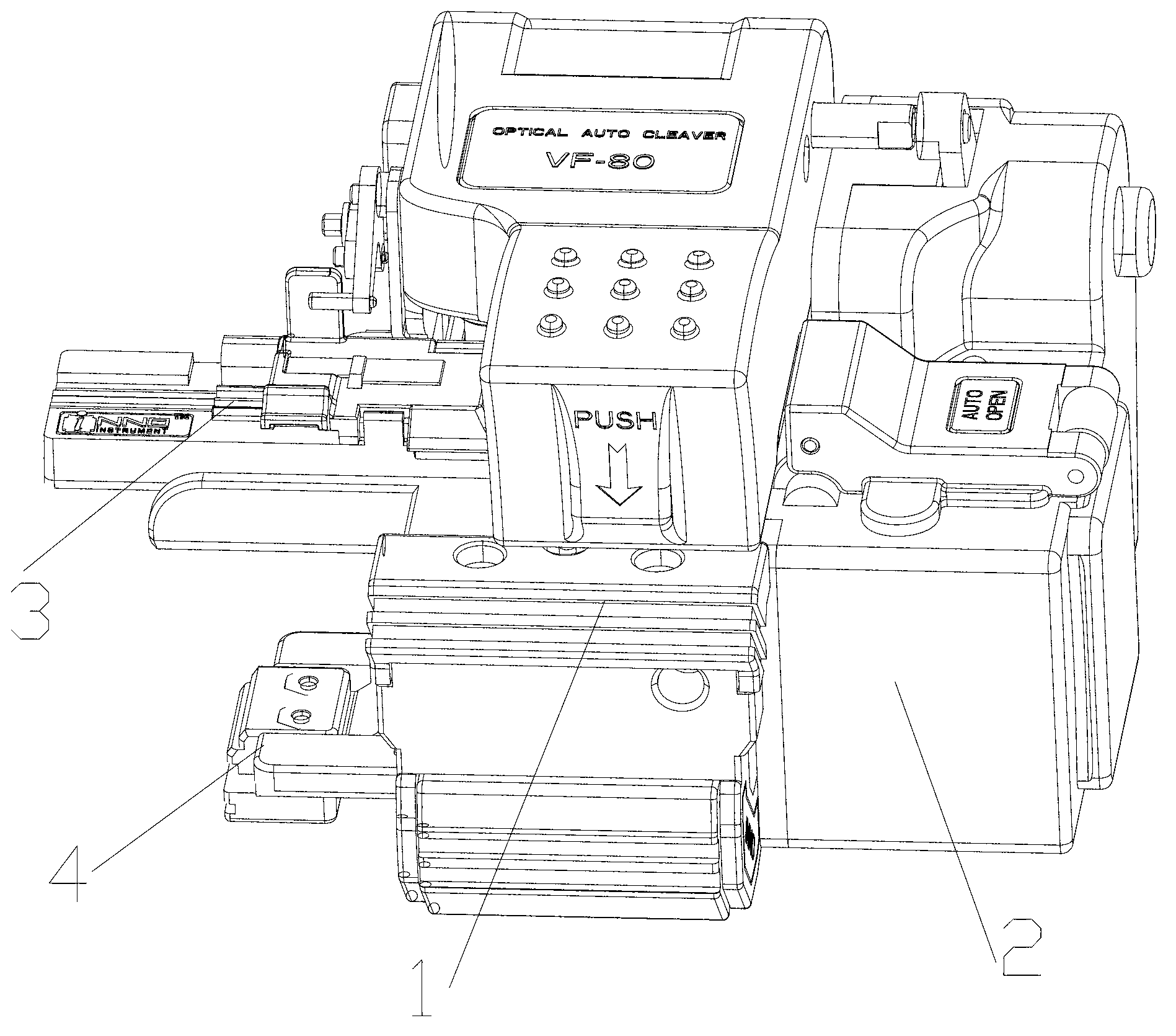
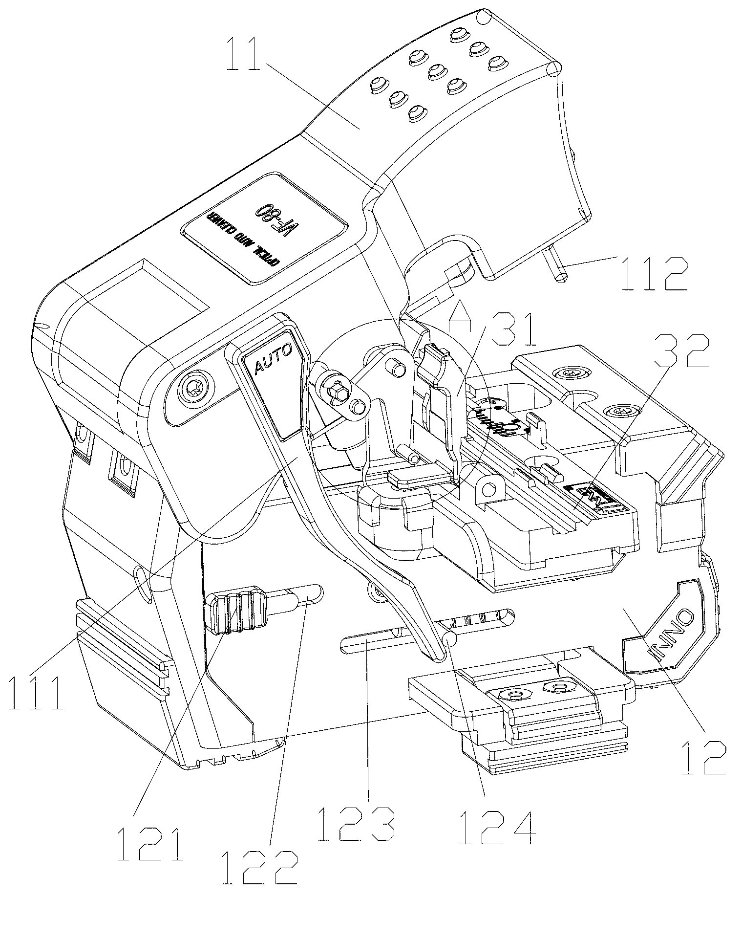
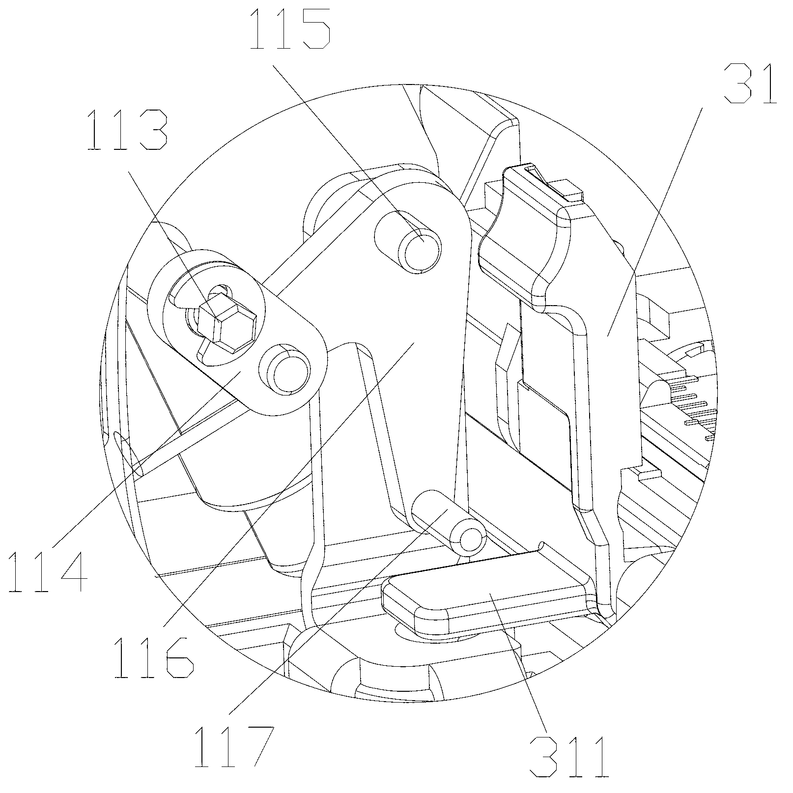
[0085]The present invention provides a fully automatic optical fiber cutter, which includes an optical fiber cutter body, an optical fiber clamp and a recoverer, the optical fiber clamp and the recoverer are respectively detachably arranged on the optical fiber cutter body, and the optical fiber cutter body includes a cutter cover and a cutter The main body, the cover of the cutter and the main body of the cutter are pivotally connected at the end, and a blade fixing seat is movably arranged in the main body of the cutter, and a blade for cutting optical fibers is arranged on the blade fixing seat; The clamp includes a clamp cover and a clamp main body, the clamp cover is pivotally connected to the clamp main body; the recoverer includes a recoverer body and a recoverer cover, and the open end of the recoverer body and the recoverer cover is provided with a fiber winding assembly corresponding to the fiber winding The component controls the fiber winding through a transmission ...


PUM


Abstract

The invention discloses a full-automatic optical fiber cutting knife which comprises an optical fiber cutting knife body and an optical fiber clamp. The optical fiber cutting knife body comprises a cutting knife cover body and a cutting knife main body which are connecting in a pivoted mode at end portions. A blade fixing seat is movably arranged inside the cutting knife main body. The blade fixing seat is provided with blades which are used for cutting optical fibers. The optical fiber clamp is arranged on the cutting knife main body. The optical fiber clamp comprises a clamp cover body and a clamp main body which are connected in a pivoted mode. The cutting knife cover body, the clamp cover body and the blade fixing seat are in linkage connection through linkage components. When the cutting knife does not work, the cutting knife cover body and the clamp cover body are opened, when the cutting knife works, the cutting knife cover body is pressed and closed, the cutting knife cover body drives the clamp cover body to be closed and pushes the blade fixing seat to move, the blades are set and used to cut the optical fibers, cutting is finished, and the cutting knife cover body bounces back and is opened. The full-automatic optical fiber cutting knife achieves full automation in true sense, operating steps are reduced, and working efficiency is improved.

Description

technical field [0001] The invention relates to an optical fiber cutter, in particular to an automatic optical fiber cutter. Background technique [0002] The optical fiber cutter is used to cut the fiber as thin as a hair. The cut fiber can be seen to be flat with a magnifying glass of several hundred times. Only the cut and flat two fibers can be discharged and connected. The steps of using a common fiber optic cleaver are generally: [0003] 1. Remove the surface coating with fiber strippers, reserve about 30-40mm, wrap the fiber with absorbent cotton dipped in alcohol, and then wipe the fiber clean; [0004] 2. Open the cover of the optical fiber clamp, open the upper cover of the optical fiber cutter, place the stripped optical fiber in the V-shaped groove of the optical fiber clamp, and determine the cutting length according to the length required by the operator; [0005] 3. Press the clamp cover to fix the fiber; [0006] 4. Close the upper cover of the cutter to ...

Claims


Application Information

Patent Timeline
IPC IPC(8): G02B6/25B26D7/02B26D7/26B26D5/08
Inventor 赵阳日
Owner INNO INSTR (CHINA) INC
Why Eureka
Try Eureka