
Full-automatic production equipment for compressor copper pipes

A production equipment, fully automatic technology, applied in other manufacturing equipment/tools, metal processing, manufacturing tools, etc., can solve the problems of low processing rate of finished pipe fittings, limited processing accuracy, easy to generate waste, etc., to achieve effective control of processing costs , Improve processing efficiency and benefit production cost

Active Publication Date: 2014-05-21
绍兴汉立工业自动化科技有限公司
View PDF5 Cites 20 Cited by
  • Summary
  • Abstract
  • Description
  • Claims
  • Application Information

AI Technical Summary

Problems solved by technology

In the conventional processing method, the aperture size and the position of the bundle head are different based on different connection parts. The original parts are usually straight copper tubes with uniform diameters. The copper tubes are processed by hand or lathe for flaring processing, and then Beam joint processing, the flaring and beam joint of the copper tube are carried out separately, the processing process is discontinuous processing, the processing efficiency is low, and the processing accuracy is limited. When the machining deformation is caused by the friction of the lathe, it is easy to produce waste, and the processing rate of the finished pipe fittings is not high.

Method used


Image

  • Full-automatic production equipment for compressor copper pipes
  • Full-automatic production equipment for compressor copper pipes
  • Full-automatic production equipment for compressor copper pipes

Examples


Embodiment 1

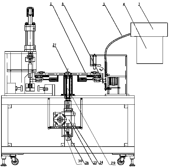
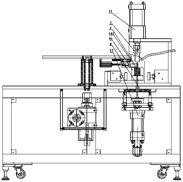
[0032] A kind of fully automatic production equipment of copper tube of compressor in this embodiment, combines figure 1 , including feeding station, flaring station, bunching station, discharging station and turntable 1, the feeding station, flaring station, bunching station and discharging station are installed on turntable 1 in sequence On the side, the bottom of the turntable 1 is equipped with a manipulator 2, which is used to move the pipe to be processed from the previous station to the next station, wherein:

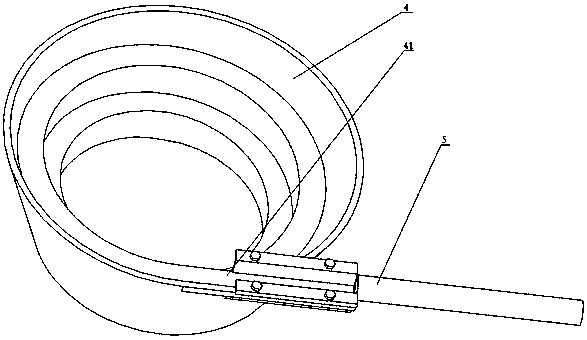
[0033] combine figure 2 , the feeding station includes a vibrating plate 3, a spiral progressive trough 4, a metal hose 5, and an accommodating sleeve 6. The spiral progressive trough 4 is located above the vibrating plate 3, and is driven by the vibrating plate 3 to vibrate. The opening 41 of the progressive trough 4 communicates with the upper end of the metal hose 5, the lower end of the metal hose 5 is located directly above the accommodating sleeve 6, the ...

Embodiment 2

[0043] The setting and working principle of this embodiment are the same as that of Embodiment 1, the difference is that the left mold 15 and the right mold 16 are composed of a mandrel 19 with high rigidity and an outer mold 20 with little rigidity, and the mandrel 19 is installed in the outer mold 20 , the matching hole is opened on the mandrel 19, the mandrel 19 is different from the outer mold 20 in rigidity, the mandrel 19 is more rigid than the outer mold 20; the second accommodation hole 102 is a through hole.

[0044] The production equipment of this embodiment is used to process copper tubes of compressors. From the aspect of processing flow, the traditional discontinuous processing is transformed into continuous automatic processing; from the aspect of input cost, under the premise of meeting the processing needs, the maximum In terms of processing efficiency and processing accuracy, the fully automated continuous production ensures the improvement of processing effic...

Embodiment 3

[0046] The arrangement and working principle of this embodiment are the same as those of Embodiment 2, the difference is that the second accommodating hole 102 is a half-through hole, and its bottom is blocked.

[0047] The production equipment of this embodiment is used to process copper tubes of compressors. From the aspect of processing flow, the traditional discontinuous processing is transformed into continuous automatic processing; from the aspect of input cost, under the premise of meeting the processing needs, the maximum In terms of processing efficiency and processing accuracy, the fully automated continuous production ensures the improvement of processing efficiency, and the cooperation of each processing station with the positioning mechanism, manipulator 2 and various power sources ensures the processing accuracy. It not only improves the qualified rate of finished products, but also reduces the scrap rate.


PUM


Abstract

The invention relates to full-automatic production equipment for compressor copper pipes, and belongs to the technical field of machining devices for compressor parts. The full-automatic production equipment for the compressor copper pipes comprises a feeding station, a flaring station, a connector binding station, a discharging station and a turntable, wherein the feeding station, the flaring station, the connector binding station and the discharging station are arranged on the side edge of the turntable in sequence, and a mechanical arm is arranged on the bottom of the turntable and is used for moving a pipe fitting to be machined from a previous station to a next station. After the pipe fitting enters through the feeding station, the pipe fitting is moved to the flaring station by the mechanical arm, flaring machining is carried out on the pipe fitting to be machined at the flaring station, the mechanical arm moves the flared pipe fitting to the connector binding station to carry out connector binding machining, then the mechanical arm moves the flared and connector bound pipe fitting to the discharging station, and thus a finished product is obtained. Through the adoption of the production equipment, full-automatic consecutive production of the feeding, the flaring, the connector binding and the discharging of the compressor copper pipes can be achieved.

Description

technical field [0001] The invention relates to a fully automatic production equipment for compressor copper tubes, belonging to the technical field of compressor component processing devices. Background technique [0002] Compressor copper pipe is a common part in refrigeration equipment. In order to meet the requirements of installation and air tightness, it usually adopts a structure with a large aperture at one end and a small aperture at the other end. At the same time, during the connection process of these components, pipe fittings and components of different materials will be connected. , such as connecting copper pipes with steel pipes, stainless steel pipes, and aluminum pipes, and then welding them firmly. Based on the requirements of welding fastness, three points, knurling, or processing beam joints will be performed on the copper pipes of the compressor. In the conventional processing method, the aperture size and the position of the bundle head are different b...

Claims


Application Information

Patent Timeline
Patent Type & Authority Applications(China)
IPC IPC(8): B23P23/02
CPCB23P23/00B23Q7/046B23Q7/10
Inventor 夏恒超付义林
Owner 绍兴汉立工业自动化科技有限公司
Learn More