Realization method of data recorder for aviation controller

A technology of a data recorder and an implementation method, applied in the directions of instruments, registration/indication, time register, etc., can solve the problem of expensive equipment and achieve the effect of improving analysis efficiency

Inactive Publication Date: 2018-09-07
安徽航瑞航空动力装备有限公司 +1
View PDF5 Cites 0 Cited by
  • Summary
  • Abstract
  • Description
  • Claims
  • Application Information

AI Technical Summary

Problems solved by technology

Professional equipment is generally more expensive and requires additional protection and securing measures

Method used


Image

  • Realization method of data recorder for aviation controller
  • Realization method of data recorder for aviation controller
  • Realization method of data recorder for aviation controller

Examples


Embodiment Construction

[0028] The specific implementation manner of the present invention will be described in further detail below by describing the best embodiment with reference to the accompanying drawings.

[0029] Feature 1: Structural design of key data recorder

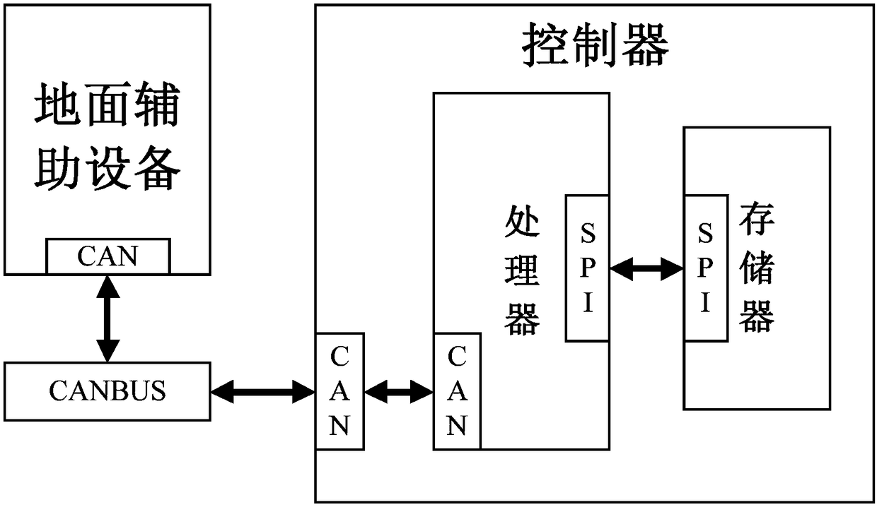
[0030] The key data recorder in the present invention is composed of two networks: one is the internal network formed by the processor and the memory through the SPI communication protocol inside the controller, and the other is the external network formed by the controller and the ground auxiliary equipment through the CAN communication protocol. In the internal network, the processor collects and recognizes key data information such as external signal information, diagnoses engine and controller faults, and identifies key events that occur in the engine, triggers SPI communication when the record activation condition is met, and records key data information into the memory . When the aircraft is on the ground and the engine is no...


PUM


Abstract

The invention discloses a realization method of a data recorder for an aviation controller. The realization method of the data recorder comprises the step of realizing the data recorder by adopting anengine controller and a memory; an inner network is composed of the controller and the memory through an SPI (Serial Peripheral Interface) communication protocol; key data information of an engine isacquired and identified through the controller, and SPI communication is triggered when recording activation conditions are met; then the key data information is recorded into the memory. The memoryis used as a recording medium, and key data including external signal data, fault information, event information and the like, which is acquired through the engine controller, is recorded in real time; the key data is transmitted into ground auxiliary equipment by designing communication based on a CAN (Controller Area Network) network, so that recording and reading of the key data information ofthe engine are ensured; the analysis efficiency of an operating condition of the engine is improved and the investigation of faults of the engine at an after-sales period is facilitated.

Description

technical field [0001] The invention relates to the technical field of development of an aero-engine control system, in particular to a method for realizing a data recorder. Background technique [0002] The engine controller is the core of the engine management system. Its function is to collect external signals and send the control commands calculated by the mathematical model to the actuator to control the stable operation of the engine. Therefore, collecting and recording engine external signal data and key control instruction data is the key to analyzing engine running status and understanding the status of engine external sensors and actuators. [0003] Most engine controllers do not have a recording function, that is, they only use the collected external signal data as part of the calculation and do not record it. If you need to realize the recording function, you generally need to install external professional equipment. Professional equipment is generally more exp...

Claims


Application Information

Patent Timeline
Patent Type & Authority Applications(China)
IPC IPC(8): G07C5/08G07C5/00
CPCG07C5/008G07C5/0808G07C5/085
Inventor 郭靖袁东东周鸿杰汪兴
Owner 安徽航瑞航空动力装备有限公司
Why Eureka
Try Eureka