Root fault cause analysis method and analysis device

A technology of analysis equipment and analysis methods, applied in digital transmission systems, electrical components, transmission systems, etc., can solve problems such as failure to eliminate network faults in time, low efficiency of fault root cause analysis, and a large amount of manpower and time

Active Publication Date: 2016-04-06
HUAWEI TECH CO LTD
View PDF4 Cites 32 Cited by
  • Summary
  • Abstract
  • Description
  • Claims
  • Application Information

AI Technical Summary

Problems solved by technology

[0004] In order to solve the above problems, an embodiment of the present invention provides a root cause analysis method and analysis equipment to solve the root cause analysis process that requires a lot of manpower and time to analyze network logs, resulting in root cause analysis The efficiency is low, and the problem of network failure cannot be eliminated in time

Method used


Image

  • Root fault cause analysis method and analysis device
  • Root fault cause analysis method and analysis device
  • Root fault cause analysis method and analysis device

Examples


Embodiment 1

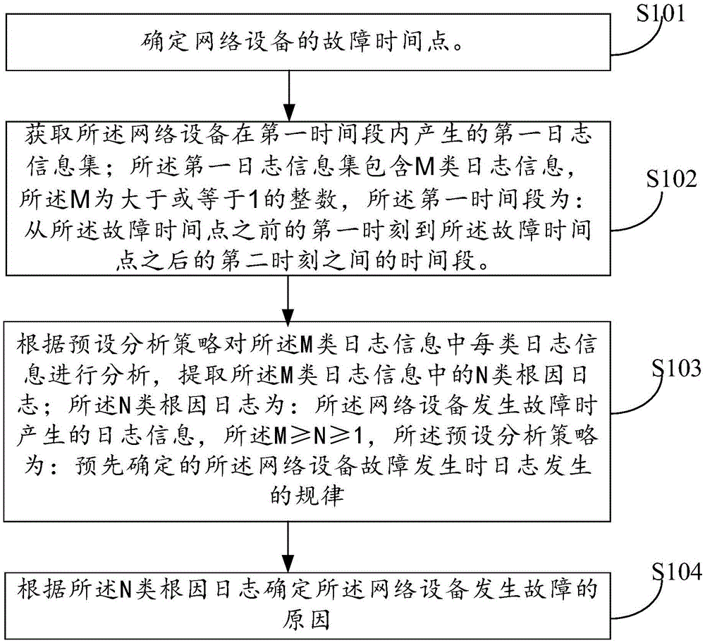
[0160] image 3 The flow chart of the failure root cause analysis method provided by the embodiment of the present invention is composed of figure 2 The analysis device 20 shown executes for the figure 2 Analysis equipment 20 in carries out failure root cause analysis, such as image 3 As shown, the method may include:

[0161] S101: Determine the failure time point of the network device.

[0162] Wherein, the failure time point is the time point when the network device fails. Since the network device may fail multiple times within a period of time, the above failure time point may refer to any time point when the network device fails once.

[0163] Optionally, the failure time point of the network equipment can be determined by using existing methods, or the failure time point of the network equipment can be located by the following method:

[0164] Obtain at least one piece of log information generated by the network device within a period of time;

[0165] Processing...

Embodiment 2

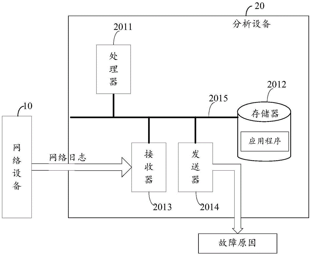
[0247] Figure 4 A structural diagram of an analysis device 30 provided in an embodiment of the present invention, the analysis device 30 may be: a switch, a router, a network management device, a Web (web page) server, a software-defined network (SoftwareDefinedNetwork, SDN) controller, etc. Any device for performing the method described in Embodiment 1, such as Figure 4 As shown, the analysis device 30 may include:

[0248] The determining unit 201 is configured to determine a failure time point of a network device.

[0249] Wherein, the failure time point is the time point when the network device fails. Since the network device may fail multiple times within a period of time, the above failure time point may refer to any time point when the network device fails once.

[0250] The obtaining unit 202 is configured to obtain a first log information set generated by the network device within a first time period; the first log information set includes M types of log informati...


PUM


Abstract

The invention discloses a root fault cause analysis method and analysis device relating to the data mining and network management field, solving the problems that in the current root fault cause analysis process, a great deal of manpower and time are used to analyze weblogs, the root fault cause analysis efficiency is relatively low, and the network fault cannot be eliminated timely. The method comprises: determining the fault time point of a network device; obtaining the first log information set generated by the network device in the first time period; wherein the first log information set comprises M kinds of log information; analyzing every kind of log information in the M kinds of log information according to a preset analysis strategy, obtaining N kinds of root cause logs in the M kinds of log information; wherein the root cause logs are log information generated when the network device generates the fault, N is more than or equal to 1 and is less than or equal to M, the preset analyzing strategy is: preset fault generation rule when the network device fault is generated; and determining the cause of generating the network device fault according to the N kinds of root cause logs.

Description

technical field [0001] The invention relates to the fields of data mining and network management, in particular to a fault root cause analysis method and analysis equipment. Background technique [0002] With the development of network technology, broadband routers are widely used in the network and occupy an important position in the network. Then, the broadband router will inevitably fail during operation. When the broadband router fails, if the cause of the failure is not determined in time and the fault is not eliminated, it will cause a temporary interruption of the network, which will bring a lot of inconvenience and loss to the enterprise. Therefore, it is necessary to determine the cause of the network failure in time and troubleshoot the broadband router. [0003] Because the network log generated by the broadband router contains most of the information related to the operation of the broadband router, therefore, those skilled in the art can locate the cause of the...

Claims


Application Information

Patent Timeline
Patent Type & Authority Applications(China)
IPC IPC(8): H04L12/24
CPCH04L41/024H04L41/0631H04L41/064
Inventor 宋跃忠林程勇张星辰谭屯子高随祥
Owner HUAWEI TECH CO LTD
Why Eureka
Try Eureka