
Road and bridge anti-collision protection device

A protection device and anti-collision technology, applied in road safety devices, roads, bridges, etc., can solve the problems of bumping against guardrails, life safety injuries, vehicles turning over and falling to the side of the road, etc., and achieving a more stable limit effect in all directions

Active Publication Date: 2018-09-11
明光市德辉木业有限公司
View PDF9 Cites 2 Cited by
  • Summary
  • Abstract
  • Description
  • Claims
  • Application Information

AI Technical Summary

Problems solved by technology

[0002] Guardrails need to be set up on the left and right sides of the road to protect the vehicle from driving and avoid falling off the roadside or under the bridge to improve safety. However, conventional guardrails cannot provide good protection. It is convenient to walk, and the height of the general road and bridge guardrail is relatively low
When the vehicle is running, in an unexpected situation, it often collides with the guardrail. In the case of a loss of control or the wrong operation of the driver, the vehicle is easy to hit the guardrail and change the direction of travel at a large angle, but hits the normal driving vehicle on the road. , or repeatedly hit the guardrail, causing serious traffic accidents, and sometimes the collision may cause the vehicle to overturn and fall to the side of the road, causing great harm to life safety

Method used


Image

  • Road and bridge anti-collision protection device
  • Road and bridge anti-collision protection device
  • Road and bridge anti-collision protection device

Examples


Embodiment Construction

[0026] The present invention will be further described in detail below in conjunction with the accompanying drawings and specific embodiments.

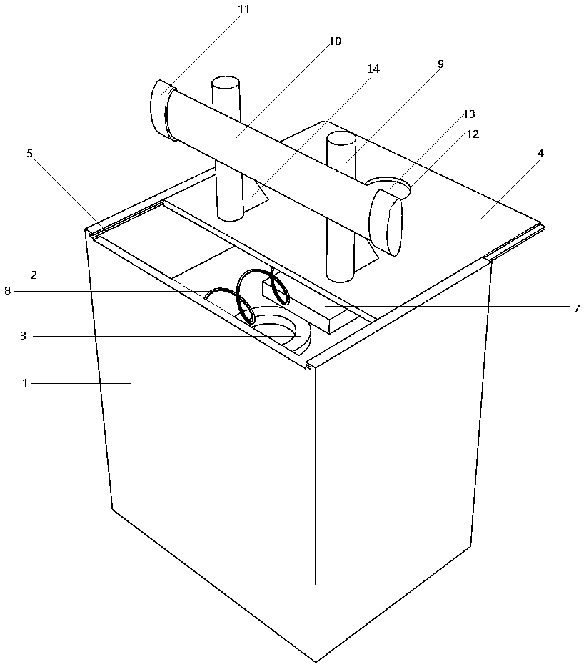
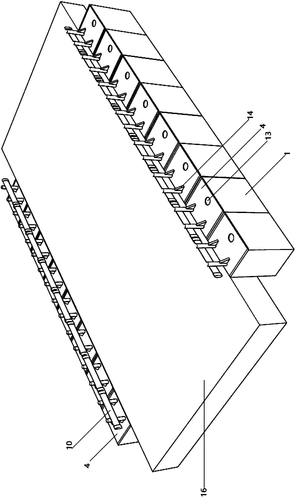
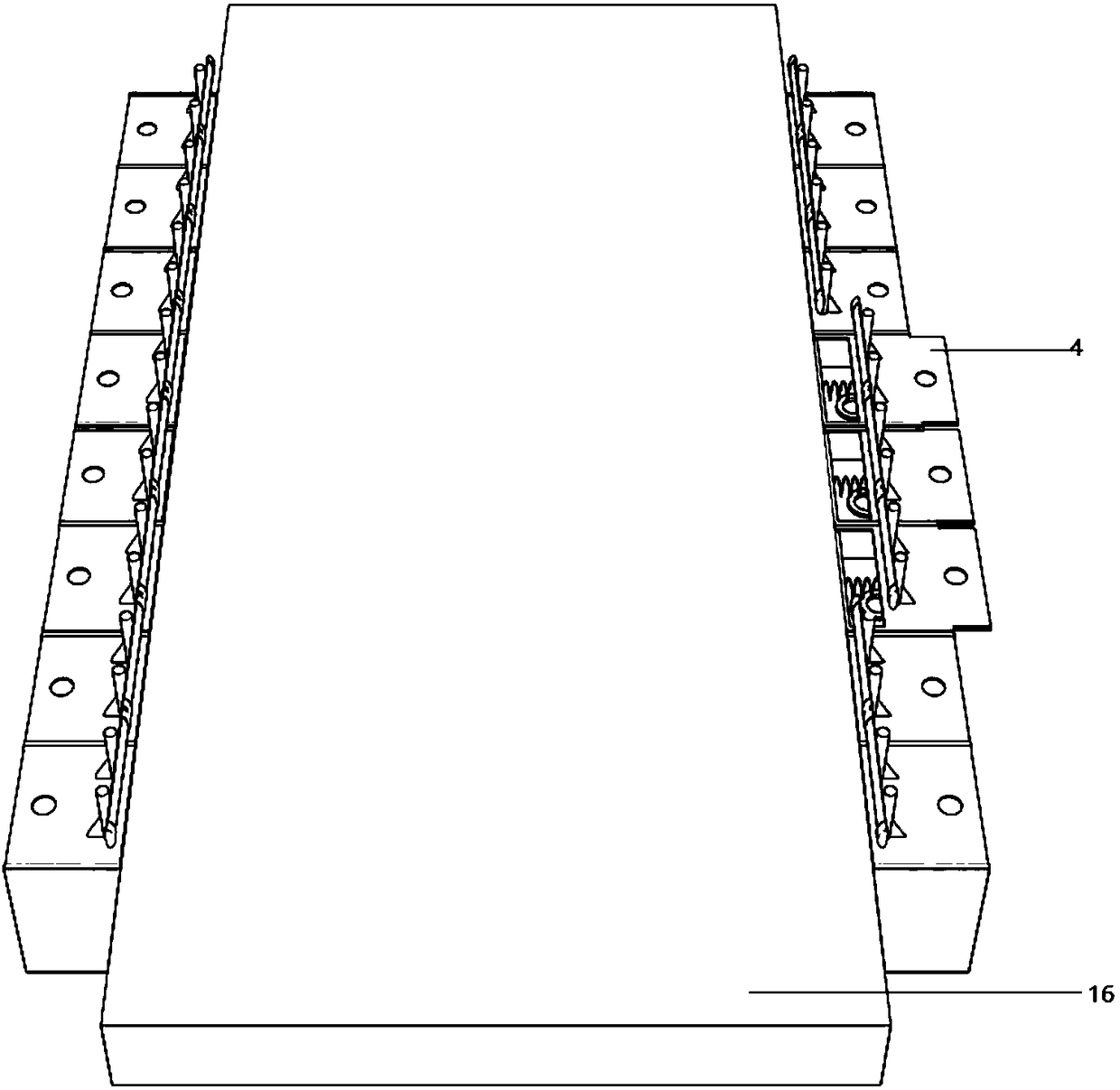
[0027] Such as Figure 1-6 As shown, a road and bridge anti-collision protection device includes protection mechanisms that are evenly arranged on the left and right sides of the road; the protection mechanism on the right side includes an installation box 1 that is fixedly connected to the side of the road; the bottom of the installation box 1 is fixedly installed There is a negative pressure box 2; the upper end of the negative pressure box 2 is provided with a connecting pipe 3; the upper end of the installation box 1 is slidingly connected with a support plate 4; Sliding connection; the middle part of the lower end of the support plate 4 is fixedly connected with a pillar 6; the lower end of the pillar 6 is fixedly connected with a sealing plate 7; the sealing plate 7 is horizontally sliding and sealingly matched with the upper en...


PUM


Abstract

The invention discloses a road and bridge anti-collision protection device, and relates to the technical field of road and bridge protection. The road and bridge anti-collision protection device comprises protection mechanisms evenly arranged on the left side and the right side of a road. The protection mechanism on the right side comprises an installation box fixedly connected with one lateral side of the road. A negative pressure box is fixedly installed at the inner bottom of the installation box. A communication pipe is arranged at the upper end of the negative pressure box. A supporting plate is slidingly connected with the upper end of the installation box. A supporting column is fixedly connected with the middle of the lower end of the supporting plate. A sealing plate is fixedly connected with the lower end of the supporting column and in horizontal sliding seal fit with the upper end face of the communication pipe. A pressing spring is fixedly installed at the upper portion ofthe left side wall in the installation box. The right end of the pressing spring is fixedly connected with the side face of the supporting column. The right end of a protection transverse plate is fixedly connected with the middle of the side face of the supporting column. The road and bridge anti-collision protection device has the advantages that a vehicle is prevented from continuously movingand random colliding when tires are indented and suspended, the vehicle is prevented from turning through the pressure intensity difference between the upper side and the lower side of the opened negative pressure box, and a protection effect is achieved.

Description

technical field [0001] The invention relates to the technical field of road and bridge protection. Background technique [0002] Guardrails need to be set up on the left and right sides of the road to protect the vehicle from driving and avoid falling off the roadside or under the bridge to improve safety. However, conventional guardrails cannot provide good protection. It is convenient to walk, and the height of the general road and bridge guardrail is relatively low. When the vehicle is running, in an unexpected situation, it often collides with the guardrail. In the case of a loss of control or the wrong operation of the driver, the vehicle is easy to hit the guardrail and change the direction of travel at a large angle, but hits the normal driving vehicle on the road. , or repeatedly hit the guardrail, causing serious traffic accidents, and sometimes the collision may cause the vehicle to overturn and fall to the side of the road, causing great harm to life safety. Co...

Claims


Application Information

Patent Timeline
IPC IPC(8): E01F15/02E01F15/04E01D19/10
Inventor 王洁邢洁姚曙光张靖川李红利邬洁白璐展德天
Owner 明光市德辉木业有限公司
Learn More