
Special liquid feeding driving device for infusion pump

A driving device and infusion pump technology, applied in measurement devices, liquid tightness measurement using liquid/vacuum degree, pressure infusion, etc., can solve the problems of reducing safety, changing infusion volume, unstable infusion volume, etc. Medical personnel and other problems, to achieve the effect of consistent infusion speed and stable infusion volume

Inactive Publication Date: 2018-09-14
JIANGSU YAKAI MEDICAL TECH CO LTD
View PDF0 Cites 0 Cited by
  • Summary
  • Abstract
  • Description
  • Claims
  • Application Information

AI Technical Summary

Problems solved by technology

[0003] However, the existing infusion lines are prone to unstable infusion speed, which leads to instability in infusion volume and difficulty in ensuring infusion accuracy, especially in micro-volume and low-speed infusions.
The reason is that the force of the pump directly acts on the pipeline, and the elasticity of different pipeline materials is different, which leads to the inappropriate fit between the pipeline and the pump body, resulting in changes in the infusion volume each time. not stable enough
[0004] Unstable infusion volume will bring a series of unnecessary troubles to patients and medical staff, increase the risk of use, and reduce the safety of infusion

Method used


Image

  • Special liquid feeding driving device for infusion pump
  • Special liquid feeding driving device for infusion pump
  • Special liquid feeding driving device for infusion pump

Examples


Embodiment

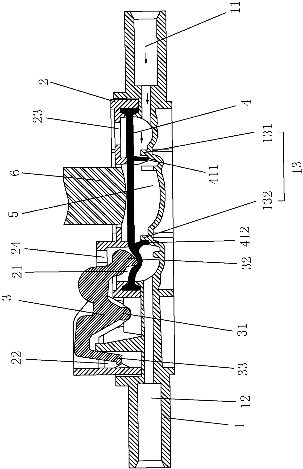
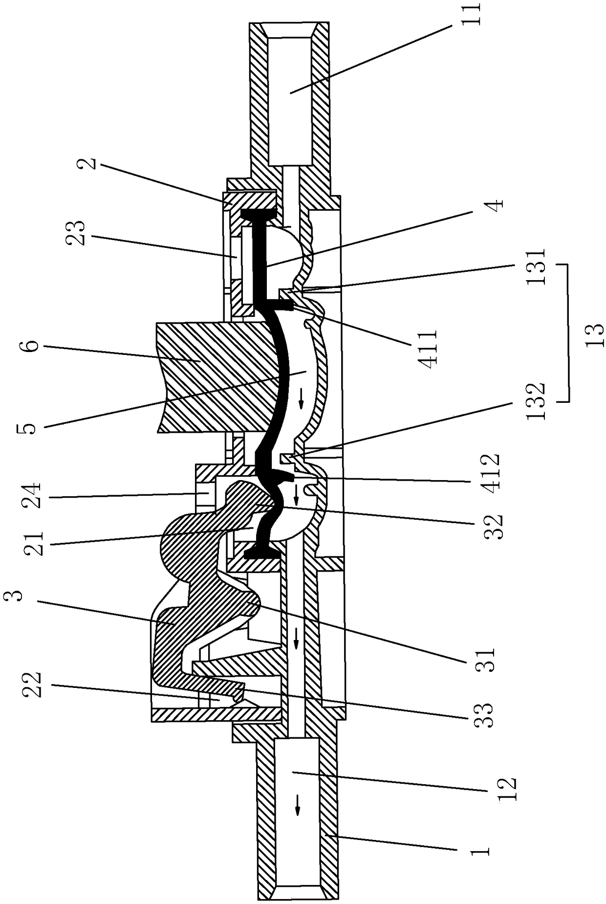
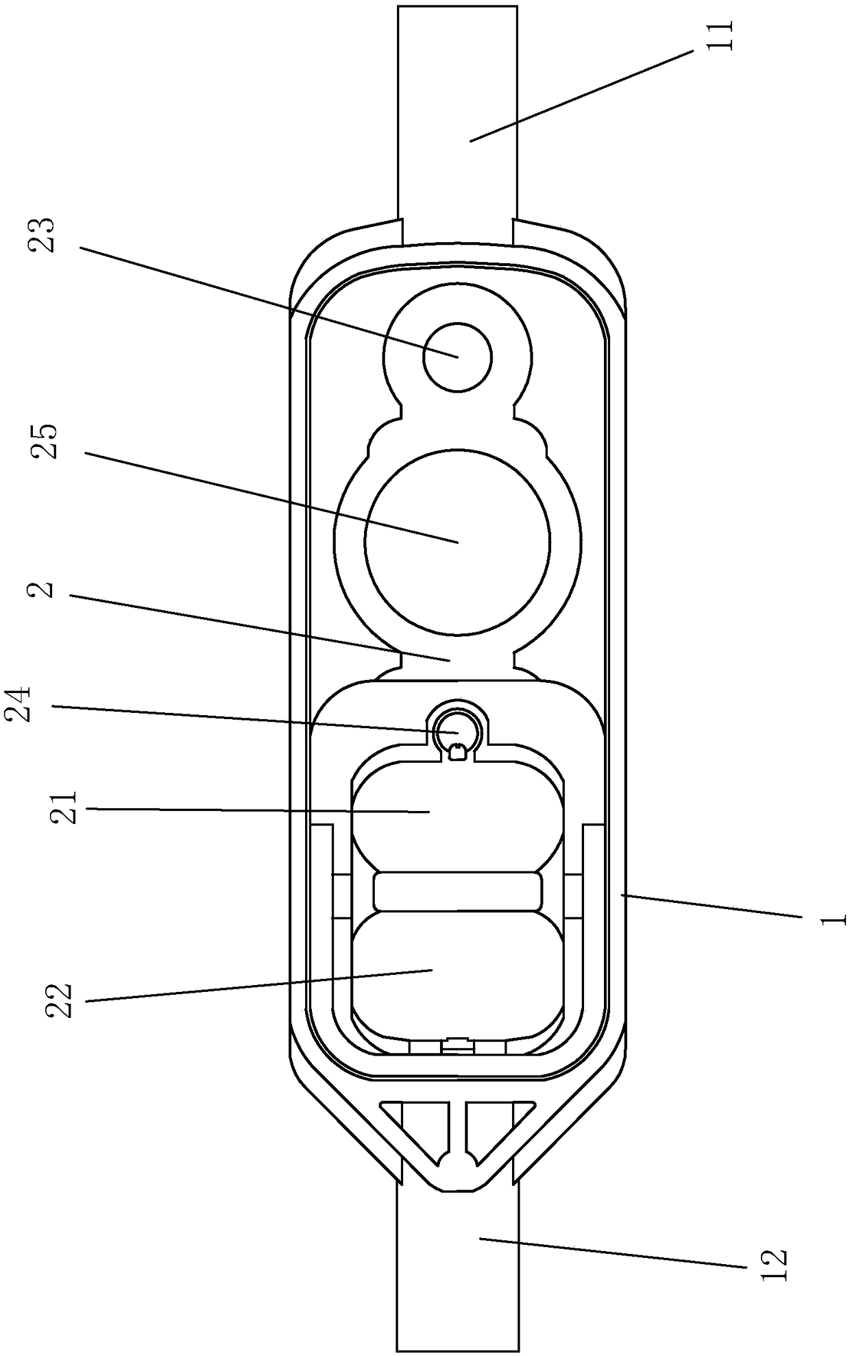
[0026] Example: Dedicated feeding drive device for infusion pump, such as figure 1 with image 3 As shown, the housing 1 is included. The middle section of the housing 1 is in the shape of a groove. The two ends of the housing 1 are respectively provided with a liquid inlet channel 11 and a liquid outlet channel 12 connecting the infusion pipeline.

[0027] An upper cover 2 is fixed on the housing 1, and a silicone valve core 4 is fixed between the housing 1 and the upper cover 2. The silicone valve core 4 is placed on the groove-shaped middle section of the housing 1 and pressed by the upper cover 2 , The two ends of the silicone valve core 4 are clamped and fixed in the positioning groove of the upper cover 2. The silicone valve core 4 is fixed to the shell 1 as a whole, and the groove-shaped middle section of the shell 1 is closed. The liquid channel 11 and the liquid outlet channel 12 are connected respectively.

[0028] The groove-shaped middle section of the housing 1 is inte...


PUM


Abstract

The invention discloses a special liquid feeding driving device for an infusion pump. According to the technical scheme, the special liquid feeding driving device for the infusion pump comprises a shell, wherein a liquid inlet channel and a liquid outlet channel are separately formed in two ends of the shell; a first lug which is close to the liquid inlet channel and a second lug which is close tothe liquid outlet channel are arranged on the shell; a silicon valve element is fixed on the shell and is provided with a first sheet and a second sheet; the first sheet is arranged at the end, whichis away from the liquid inlet channel, of the first lug; the second sheet is arranged at the end, which is close to the liquid outlet channel, of the second lug; a liquid storage space is formed by the shell and the silicon valve element and positioned between the first lug and the second lug; when the first sheet is attached to the first lug, the liquid inlet channel is isolated from the liquidstorage space; and when the second sheet is attached to the second lug, the liquid storage space is isolated from the liquid outlet channel. The special liquid feeding driving device for the infusionpump is further provided with a switch for controlling attachment between the second sheet and the second lug, and the surface, which is away from the liquid storage space, of the silicon valve element faces a push rod of the infusion pump. The special liquid feeding driving device for the infusion pump has the advantages that the infusion quantity can become stable, and stability of intravenous infusion is improved.

Description

Technical field [0001] The invention relates to the field of sterile medical devices, and in particular to a special liquid feeding drive device for an infusion pump. Background technique [0002] The infusion pipelines for infusion pumps used for patients in hospitals are mostly polymer pipelines such as intravenous infusion sets and nutritional infusion sets. The characteristics of the use of such pump pipelines are the force provided by the pump. Directly act on the infusion pipeline to supply the infusion energy. [0003] However, the existing infusion pipeline is prone to the problem of unstable infusion rate, which leads to the instability of the infusion volume, and the accuracy of the infusion is difficult to guarantee, especially in the micro-low-rate infusion. The reason is mainly because the force of the pump directly acts on the pipeline, and the elasticity of different pipeline materials is different, resulting in the pipeline and the pump body being not in place, res...

Claims


Application Information

Patent Timeline
Patent Type & Authority Applications(China)
IPC IPC(8): A61M5/142A61M5/168G01M3/28
CPCA61M5/142A61M5/16813A61M5/16877A61M2205/3334G01M3/2815
Inventor 毛爱民
Owner JIANGSU YAKAI MEDICAL TECH CO LTD
Learn More