
Novel pile insertion construction device

A construction device and pile insertion technology, applied in sheet pile walls, foundation structure engineering, construction, etc., can solve the problems of inaccessibility of large machinery, low efficiency of manual pile insertion, laborious and other problems, and achieve novel concept, ingenious structure, and simple operation Effect

Inactive Publication Date: 2018-09-18
安徽华瓴建工集团有限公司
View PDF2 Cites 2 Cited by
  • Summary
  • Abstract
  • Description
  • Claims
  • Application Information

AI Technical Summary

Problems solved by technology

[0003] In view of the above situation, in order to solve the problems existing in the prior art, the purpose of the present invention is to provide a new type of piling construction device, which can easily enter the construction site, and can change the striking force according to the actual needs of the foundation soil to meet different hardness requirements. The needs of the foundation make the pile insertion process labor-saving, easy to operate, and good in safety, which can effectively solve the problems of inaccessible large-scale machinery in the prior art, low efficiency and laborious manual pile insertion

Method used


Image

  • Novel pile insertion construction device
  • Novel pile insertion construction device
  • Novel pile insertion construction device

Examples


Embodiment Construction

[0016] The specific implementation manners of the present invention will be described in further detail below in conjunction with the accompanying drawings.

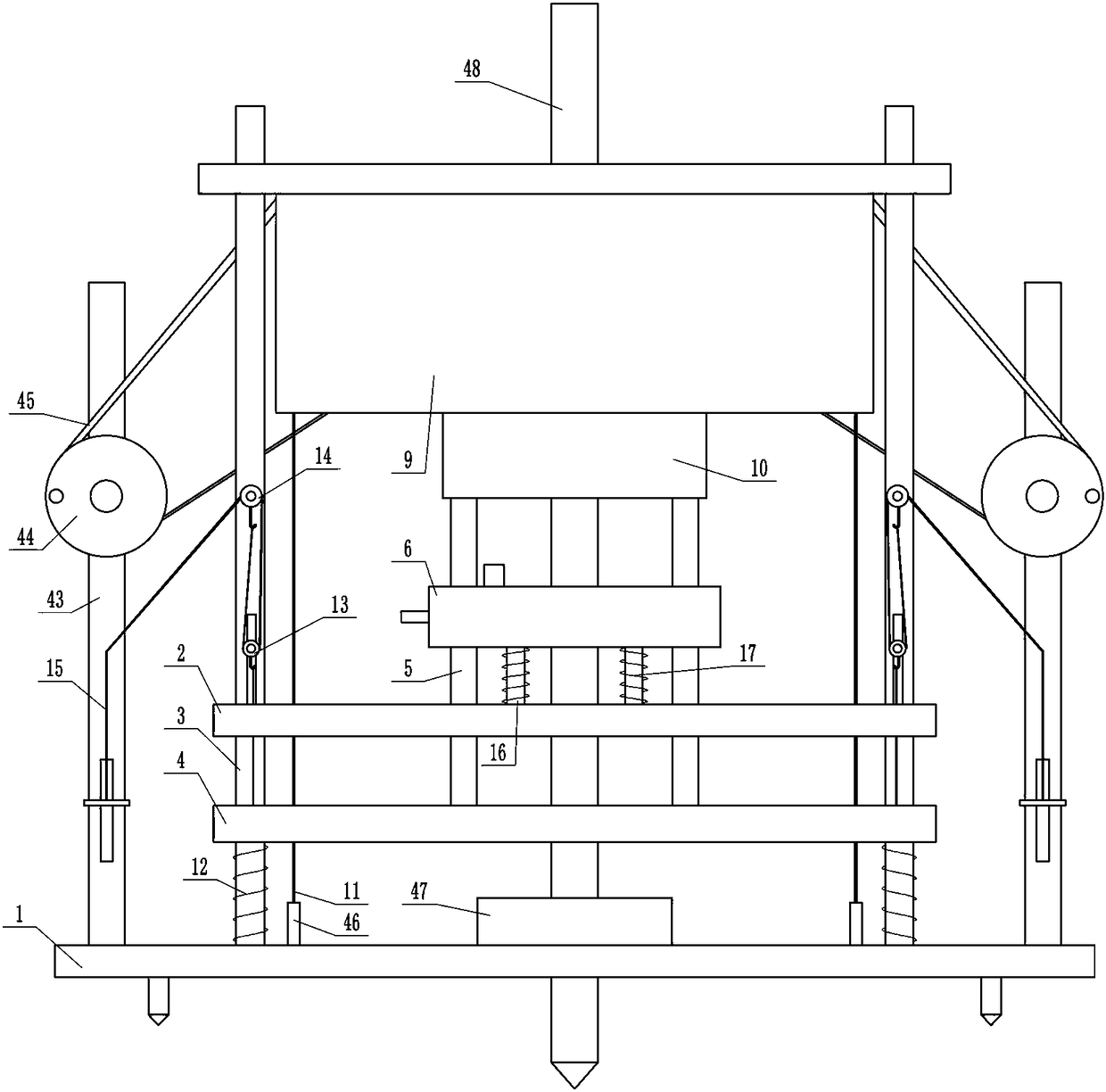
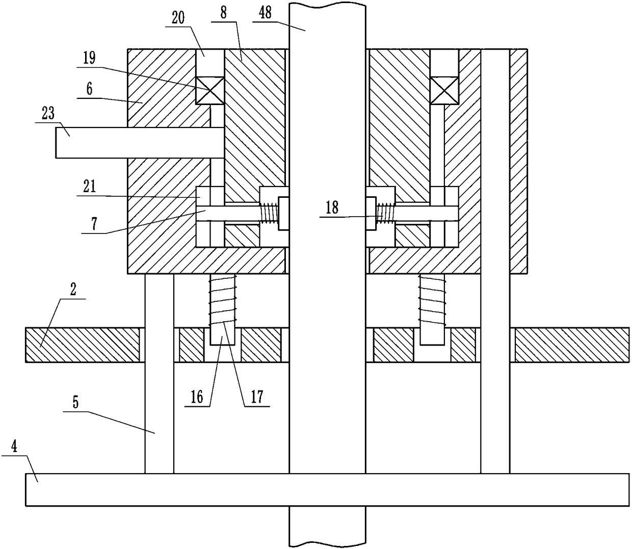
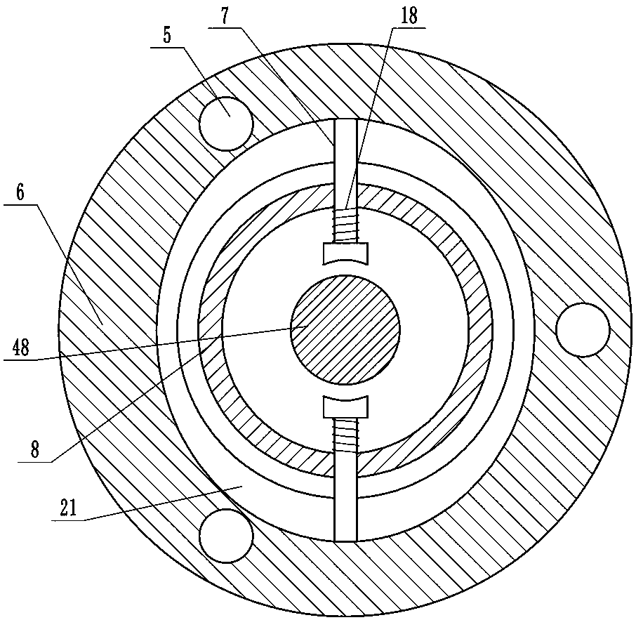
[0017] Depend on Figure 1 to Figure 9 Provided, the present invention comprises a horizontal first flat plate 1, above the first flat plate 1 there is a third flat plate 2 parallel to the first flat plate 1, a plurality of upper ends of the first flat plate 1 pass through the third flat plate 2 and The vertical bar 3 above the third flat plate 2, a second flat plate 4 that can move up and down along the vertical bar 3 is arranged on the vertical bar 3 between the first flat plate 1 and the third flat plate 2, the first flat plate 1, the second flat plate 4 and the third plate 2 have a through hole with the axis coincident, and the second plate 4 has a plurality of vertical first push rods 5 whose upper ends pass through the third plate 2 and are located above the third plate 2. A push rod 5 is fitted with a first sleev...


PUM


Abstract

The invention relates to a novel pile insertion construction device. The novel pile insertion construction device effectively solves the problem that in the prior art, a large machine cannot enter theconstruction site, and therefore manual pile insertion efficiency is low and labor is wasted. The technical scheme of the novel pile insertion construction device is characterized by comprising a first flat plate, wherein a third flat plate is arranged above the first flat plate, vertical rods are arranged on the first flat plate, a second flat plate is arranged on the vertical rods, the first flat plate is provided with through holes, the second flat plate is provided with through holes, and the third flat plate is provided with through holes; first push rods are arranged on the second flatplate, a first sleeve is arranged on the first push rods, a second sleeve is arranged in the first sleeve, second push rods are arranged on the side wall of the second sleeve, and a clamping device isarranged between each second push rod and the first sleeve; and a third sleeve is arranged above the first sleeve, a hammer head is arranged in the third sleeve, a through hole is formed in the center of the hammer head, a fixing device is arranged between the hammer head and the third sleeve, and first ropes are arranged on the fixing device. The novel pile insertion construction device has theadvantages that pile bodies can be clamped and loosened in the pile insertion process, and meanwhile, the rising height of the hammer head can be adjusted according to the requirements of the actual foundation soil quality so that requirements of foundations with different hardness can be met.

Description

technical field [0001] The invention relates to water conservancy equipment, in particular to a novel pile-inserting construction device. Background technique [0002] Wooden piles play an important role in flood control, but the existing pile-inserting machines mostly use heavy machinery, but heavy machinery cannot enter many small construction sites, which affects the construction process. When heavy machinery cannot enter the construction site, it is up to the staff to Knocking wooden piles into the ground is inefficient and laborious. Therefore, a new type of pile insertion construction device is urgently needed, which can easily enter the construction site, and can change the striking force according to the actual needs of the foundation soil to meet different hardness requirements. The needs of the foundation, and the whole piling process is labor-saving, easy to operate, and safe. Contents of the invention [0003] In view of the above situation, in order to solve ...

Claims


Application Information

Patent Timeline
IPC IPC(8): E02D7/08E02D7/14E02D7/16
CPCE02D7/08E02D7/14E02D7/16
Inventor 贾羽威
Owner 安徽华瓴建工集团有限公司
Learn More