Inner diameter detecting device of circular pipe

A detection device and pipeline technology, applied in the direction of mechanical diameter measurement, etc., can solve the problem of inaccurate detection and achieve accurate measurement results, accurate detection, and accurate data

Active Publication Date: 2018-09-18
温州瑞智门窗有限公司
View PDF10 Cites 5 Cited by
  • Summary
  • Abstract
  • Description
  • Claims
  • Application Information

AI Technical Summary

Problems solved by technology

[0006] In order to overcome the disadvantage that it is difficult to fix the pipeline during manual detection, resulting in inaccurate detection, the technical problem to be solved by the invention is to provide a circular pipeline inner diameter detection device that can fix the pipeline and make the detection more accurate

Method used


Image

  • Inner diameter detecting device of circular pipe
  • Inner diameter detecting device of circular pipe
  • Inner diameter detecting device of circular pipe

Examples


Embodiment 1

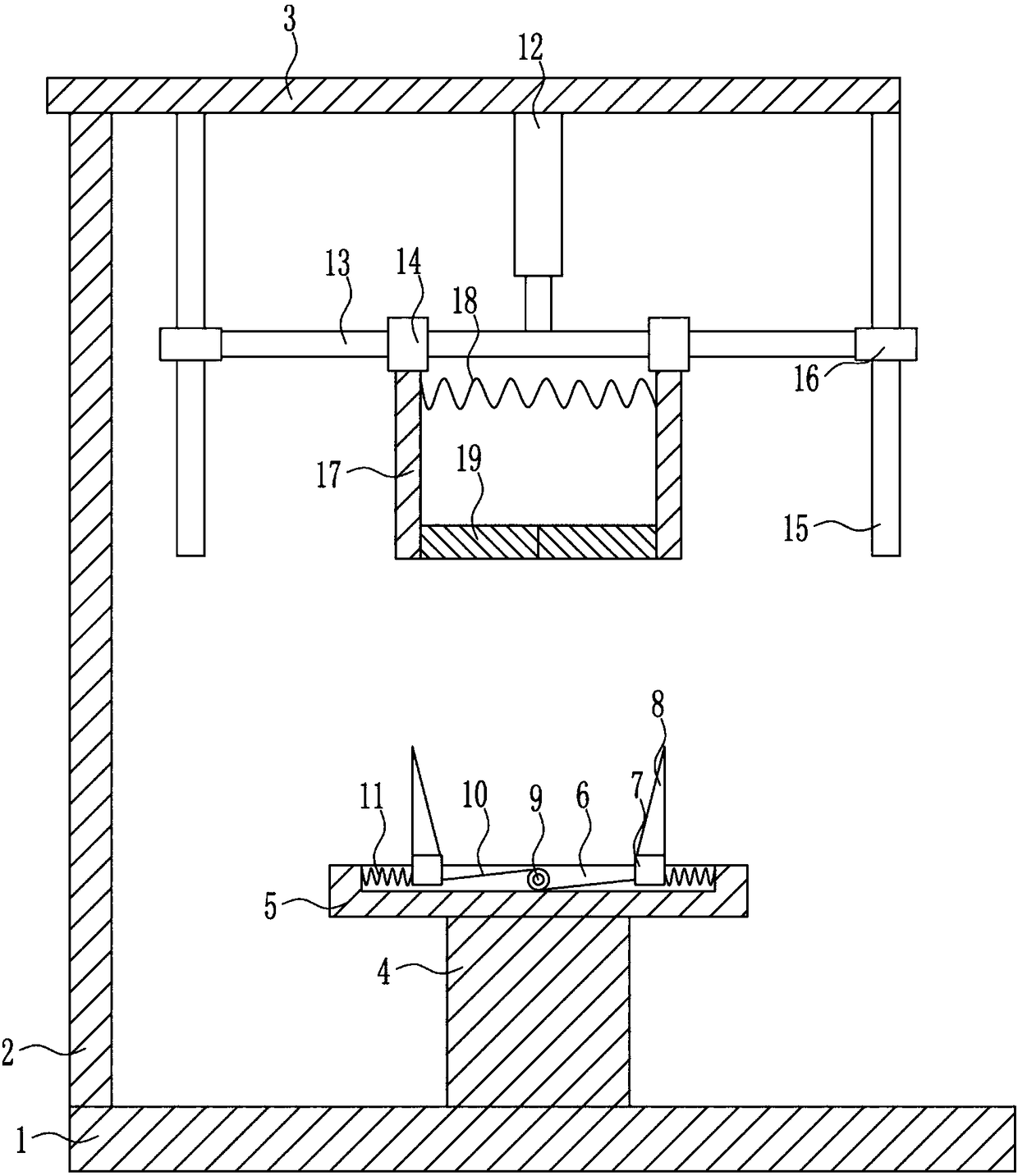
[0025] A circular pipe inner diameter detection device, such as Figure 1-4 As shown, it includes bottom plate 1, left bracket 2, top plate 3, support 4, fixed plate 5, first slider 7, limit rod 8, electric reel 9, pull wire 10, first spring 11, electric push Rod 12, first guide rod 13, first guide sleeve 14, second guide rod 15, second guide sleeve 16, vertical rod 17, second spring 18 and arc splint 19, left bracket is provided on the left side of the bottom plate 1 top 2. There is a top plate 3 on the top of the left bracket 2, and an electric push rod 12 is installed in the middle of the bottom of the top plate 3. The bottom end of the electric push rod 12 is connected with a first guide rod 13, and two first guide sleeves are arranged on the first guide rod 13 14. The left and right sides of the bottom of the top plate 3 are provided with second guide rods 15, and the second guide rods 15 are provided with second guide sleeves 16. The left and right ends of the first guid...

Embodiment 2

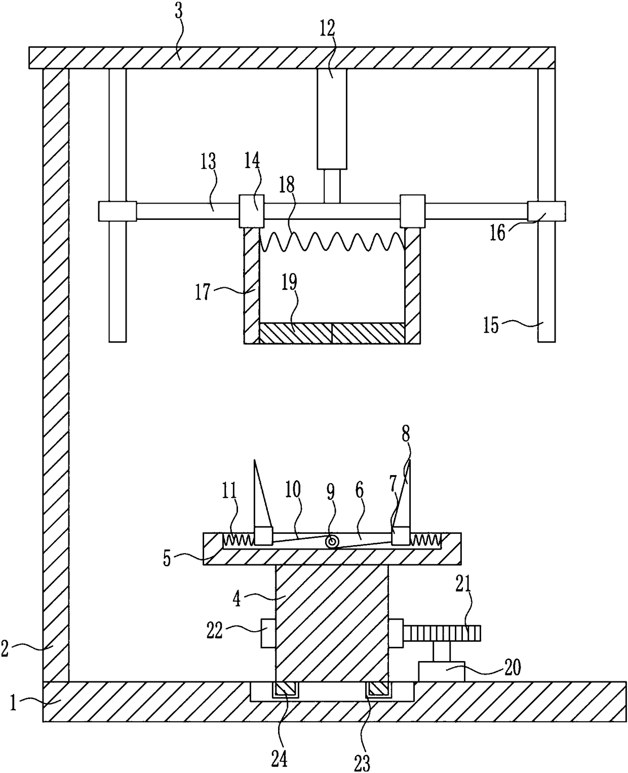
[0027] A circular pipe inner diameter detection device, such as Figure 1-4 As shown, it includes bottom plate 1, left bracket 2, top plate 3, support 4, fixed plate 5, first slider 7, limit rod 8, electric reel 9, pull wire 10, first spring 11, electric push Rod 12, first guide rod 13, first guide sleeve 14, second guide rod 15, second guide sleeve 16, vertical rod 17, second spring 18 and arc splint 19, left bracket is provided on the left side of the bottom plate 1 top 2. There is a top plate 3 on the top of the left bracket 2, and an electric push rod 12 is installed in the middle of the bottom of the top plate 3. The bottom end of the electric push rod 12 is connected with a first guide rod 13, and two first guide sleeves are arranged on the first guide rod 13 14. The left and right sides of the bottom of the top plate 3 are provided with second guide rods 15, and the second guide rods 15 are provided with second guide sleeves 16. The left and right ends of the first guid...

Embodiment 3

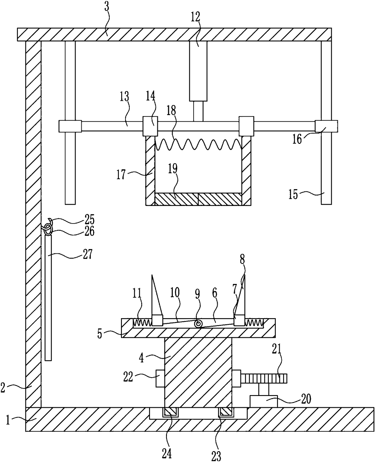
[0030] A circular pipe inner diameter detection device, such as Figure 1-4As shown, it includes bottom plate 1, left bracket 2, top plate 3, support 4, fixed plate 5, first slider 7, limit rod 8, electric reel 9, pull wire 10, first spring 11, electric push Rod 12, first guide rod 13, first guide sleeve 14, second guide rod 15, second guide sleeve 16, vertical rod 17, second spring 18 and arc splint 19, left bracket is provided on the left side of the bottom plate 1 top 2. There is a top plate 3 on the top of the left bracket 2, and an electric push rod 12 is installed in the middle of the bottom of the top plate 3. The bottom end of the electric push rod 12 is connected with a first guide rod 13, and two first guide sleeves are arranged on the first guide rod 13 14. The left and right sides of the bottom of the top plate 3 are provided with second guide rods 15, and the second guide rods 15 are provided with second guide sleeves 16. The left and right ends of the first guide...


PUM


Abstract

The invention relates to a detecting device, in particular to an inner diameter detecting device of a circular pipe so that a pipe can be fixed and detection can be realized accurately. The inner diameter detecting device is composed of a bottom plate, a left bracket, a top plate, a support base, a fixed plate, a first sliding block, a limit rod, an electric reel, a pulling wire, a first spring, an electric push rod, and a first guide rod and the like. The left bracket is arranged at the left side of the top of the bottom plate; the top plate is arranged on the top of the left bracket; the electric push rod is arranged in the middle of the bottom of the top plate; the first guide rod is connected to the bottom of the electric push rod; and two first guide sleeves arranged at the first guide rod. According to the invention, the circular pipe is clamped firmly by an arc clamp rod and the inner diameter of the pipe is measured by the limit rod. Therefore, the inner diameter can be measured visually and the measuring result is accurate; the pipe can be fixed; and the detection accuracy is high.

Description

technical field [0001] The invention relates to a detection device, in particular to a detection device for the inner diameter of a circular pipeline. Background technique [0002] Detection is to use the specified method to test the specified technical performance indicators of an object (gas, liquid, solid). It is suitable for quality assessment in various industries, such as: civil engineering, water conservancy, food, chemistry, environment, machinery, machines, etc. [0003] A pipeline is a device used to transport gas, liquid or fluid with solid particles connected by pipes, pipe connectors and valves. Usually, after the fluid is pressurized by blowers, compressors, pumps and boilers, it flows from the high-pressure part of the pipeline to the low-pressure part, and it can also be transported by the pressure or gravity of the fluid itself. Pipes are widely used, mainly in water supply, drainage, heat supply, gas supply, long-distance transportation of oil and natural...

Claims


Application Information

Patent Timeline
Patent Type & Authority Applications(China)
IPC IPC(8): G01B5/12
CPCG01B5/12
Inventor 钟维栋罗圆王飘逸
Owner 温州瑞智门窗有限公司
Why Eureka
Try Eureka