
Intelligent instant freezer

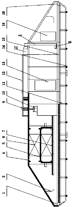
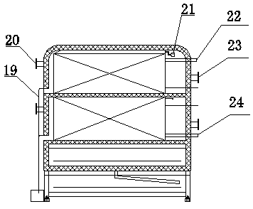
A kind of quick freezer, intelligent technology, applied in the direction of cooling machine, lighting and heating equipment, defrosting, etc., can solve the problems of reducing work efficiency, difficulty in operation, increasing energy consumption of refrigerators, etc., to reduce maintenance costs and ensure normal operation. , to avoid the effect of downtime defrosting

Pending Publication Date: 2018-09-21
山东滨州冰天制冷设备有限公司
View PDF6 Cites 3 Cited by
  • Summary
  • Abstract
  • Description
  • Claims
  • Application Information

AI Technical Summary

Problems solved by technology

[0003] However, the current quick-freezers have the following problems in use. First, during the production and operation of the quick-freezer, the surface of the finned tubes of the evaporator is in the state of air dehumidification and negative temperature. Under this working condition, the thickness of frost on the surface of the finned tubes The continuous increase will eventually lead to blockage of the air passage between the fins and reduce the heat transfer area, resulting in reduced heat transfer efficiency, worsened air circulation, increased freezing temperature and difficult operation. Generally, if it lasts for 8 hours or longer, production must be stopped for defrosting and re-cooling to ensure normal production, which reduces work efficiency, and at the same time, for frozen products, stopping refrigeration will cause damage, and the re-refrigerating time will be longer, which will also affect frozen products; at the same time, the axial flow fan of the existing refrigerator is generally set Inside the refrigerator, the fan will generate heat during operation, which will increase the energy consumption of the refrigerator, and the heat generated by the heat will also cause energy loss

Method used


Image

  • Intelligent instant freezer
  • Intelligent instant freezer
  • Intelligent instant freezer

Examples


Embodiment Construction

[0021] In order to make the purpose, technical solutions and advantages of the embodiments of the present invention clearer, the technical solutions in the embodiments of the present invention will be clearly and completely described below in conjunction with the drawings in the embodiments of the present invention. Obviously, the described embodiments It is a part of embodiments of the present invention, but not all embodiments. The components of the embodiments of the invention generally described and illustrated in the figures herein may be arranged and designed in a variety of different configurations. Accordingly, the following detailed description of the embodiments of the invention provided in the accompanying drawings is not intended to limit the scope of the claimed invention, but merely represents selected embodiments of the invention. Based on the embodiments of the present invention, all other embodiments obtained by persons of ordinary skill in the art without cre...


PUM


Abstract

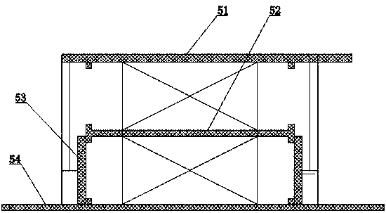
The invention relates to an intelligent instant freezer, which comprises a freezer body and an outer support frame arranged at the lower end of the freezer body, wherein a refrigeration mechanism is arranged in the machine body and comprises two evaporators, an evaporator separation plate, evaporator door plates and an air return baffle plate, wherein the two evaporators are arranged in a separated way at upper side and lower side through the evaporator separation plate; the evaporator door plates are movably arranged at the two sides of one of the two evaporators; the upper end of the machinebody is provided with a dismounting type centrifugal fan; the lower end of the centrifugal fan is connected with an air return air collecting cover positioned inside the machine body; an externally-mounted fan over is arranged at the outer side of the dismounting type centrifugal fan, and is communicated with the lower end of the machine body through a hot air pipeline; a pipeline fan is arrangedon the hot air pipeline. The instant freezer has the advantages that the defrosting on the instant freezer can be realized under the condition without machine halt; the continuity of the freezing isensured; the freezing effect is ensured; through a fan externally-installation technology, the freezing effect is not influenced; the recovery and utilization of the fan heat is realized; the production cost is reduced.

Description

technical field [0001] The invention relates to the technical field of refrigeration equipment, in particular to an intelligent quick-freezing machine. Background technique [0002] Quick freezer is a high-efficiency freezing equipment that can freeze a large amount of products in a short time. It can effectively and economically freeze a variety of products placed inside the quick freezer, such as various shapes of meat, fish, shrimp, meatballs, vegetables, prepared foods, dairy products, etc. [0003] However, the current quick-freezing machine has the following problems in use. First, during the production and operation of the quick-freezing machine, the surface of the finned tube of the evaporator is in the state of air dehumidification and negative temperature. Under this working condition, the thickness of frost on the surface of the finned tube The continuous increase will eventually lead to blockage of the air passage between the fins and reduce the heat transfer ar...

Claims


Application Information

Patent Timeline
Patent Type & Authority Applications(China)
IPC IPC(8): F25D13/06F25D21/06
CPCF25D13/06F25D21/06
Inventor 康景隆刘永江马坤贾俊伟代立军杨艳如牛鹏夏玉先刘洪卫孙超高俊亮傅合建
Owner 山东滨州冰天制冷设备有限公司
Learn More