Experimental device and test method for studying two-dimensional and three-dimensional seepage and soil particle erosion law

A test device and seepage technology, which is used in measurement devices, permeability/surface area analysis, suspension and porous material analysis, etc. It can solve the problems that scholars rarely involve and achieve the effect of visualization

Inactive Publication Date: 2018-09-21
HUATIAN ENG & TECH CORP MCC
View PDF8 Cites 8 Cited by
  • Summary
  • Abstract
  • Description
  • Claims
  • Application Information

AI Technical Summary

Problems solved by technology

For the indoor experimental research on the seepage damage of embankment foundation with two-dimensional str

Method used


Image

  • Experimental device and test method for studying two-dimensional and three-dimensional seepage and soil particle erosion law
  • Experimental device and test method for studying two-dimensional and three-dimensional seepage and soil particle erosion law
  • Experimental device and test method for studying two-dimensional and three-dimensional seepage and soil particle erosion law

Examples


Embodiment 1

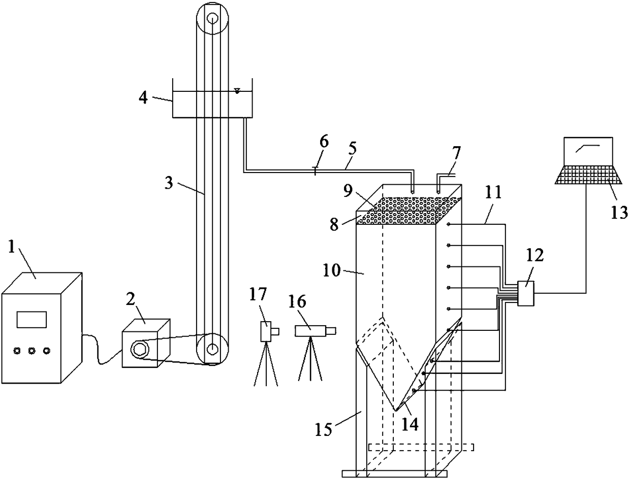
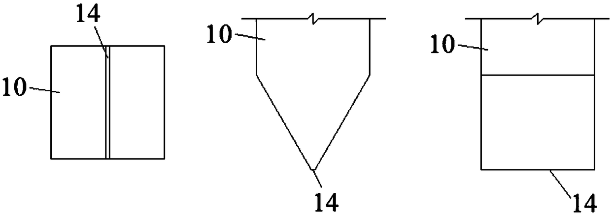
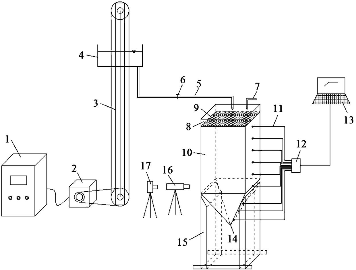
[0032] combine figure 1 and figure 2 , the present embodiment provides a kind of test device for studying two-dimensional seepage-soil particle erosion rule, including steel bracket 15, a test box arranged on the steel bracket 15, a sand separation net 9 arranged in the test box, and a Intelligent water head for adding water to the box; the sand separation net is arranged in the test box along the horizontal direction, and the test box is divided into the upper water inlet area 8 and the lower sample area 10, and the upper part of the water inlet area 8 is equipped with an exhaust A hole 7; a water outlet 14 is provided at the bottom of the test box. In this embodiment, the bottom of the test chamber is V-shaped, and the water outlet 14 is arranged at the bottom of the V-shape. The shape of the water outlet 14 is a long and narrow rectangle with a width of 5 mm.

[0033] A number of water pressure sensors 11 are arranged on the side wall of the test box corresponding to the...

Embodiment 2

[0036] As a specific solution of Embodiment 1, the intelligent water head in this embodiment includes a water tank 4 and a lifting device for controlling the lifting of the water tank. The bottom of the water tank 4 is provided with a water outlet pipe 5, and the water outlet pipe 5 is provided with a flow regulating valve 6. The water outlet pipe The water outlet of 5 is corresponding to the water inlet area 8 of described test box;

[0037] The lifting device includes a support frame, a drive motor 2, a first fixed pulley and a second fixed pulley wound around the support frame at a predetermined distance along the vertical direction, and a conveyor belt is arranged between the first fixed pulley and the second fixed pulley 3. The water tank 4 is set on the conveyor belt and moves up and down along with the conveyor belt; the output shaft of the drive motor 2 is connected to the first fixed pulley through a belt to drive the first fixed pulley to rotate; in this embodiment T...

Embodiment 3

[0039] As a further improvement of Embodiment 1, in this embodiment, the water outlet 14 is provided with a first flow measuring device for detecting the amount of water gushing and a second flow detecting device for detecting the amount of sand gushing, and the bottom of the water outlet 14 is also provided with Sand tray.


PUM


Abstract

The invention discloses an experimental device for studying two-dimensional and three-dimensional seepage and soil particle erosion law, including a steel support, a test box arranged on the steel support, a sand screen arranged inside the test box and an intelligent water tap for adding water to the test box; the sand screen is arranged inside the test box along horizontal direction and divides the test box into an upper water inlet area and a lower sample area; the bottom of the test box is provided with a water outlet; a plurality of water pressure sensors are arranged on side walls corresponding to sample area of the test box and each water pressure sensor is connected with a computer terminal in communication junction. The experimental device and a test method for studying two-dimensional and three-dimensional seepage and soil particle erosion law can relatively and accurately reflect the erosion process and law of soil under seepage function.

Description

technical field [0001] The invention relates to a test method for studying osmotic damage and a test device for implementing the osmotic damage research method, and belongs to the field of hydraulic engineering osmotic damage test methods and experimental instruments. Background technique [0002] Infiltration is the process of seepage due to the uneven pressure of groundwater, and infiltration will cause the migration and loss of sand particles. A large number of flood disaster data show that the seepage of embankment foundation and embankment body is the most harmful to river embankment and dam. In order to ensure the safety of embankment engineering, the problem of seepage damage has been widely concerned by the academic and engineering circles. It is of great significance to study the process and law of embankment seepage-soil particle erosion to prevent seepage damage and propose corresponding prevention and control measures. [0003] In the process of studying the occ...

Claims


Application Information

Patent Timeline
IPC IPC(8): G01N15/08G01N15/00
CPCG01N15/00G01N15/08G01N15/0806G01N15/0826G01N2015/0846
Inventor 王霜陈超周鹏刘彦辰陈祥勇
Owner HUATIAN ENG & TECH CORP MCC
Why Eureka
Try Eureka