System and Method for Crossflow Detection and Intervention in Production Wellbores

Inactive Publication Date: 2008-10-23
BAKER HUGHES INC
View PDF49 Cites 73 Cited by
  • Summary
  • Abstract
  • Description
  • Claims
  • Application Information

AI Technical Summary

Benefits of technology

[0008]Upon detection or based on the predicted cross flow, the method may determine changes that may be made to the operation of one or more devices, which changes when made may reduce or eliminate the cross flow condition or its effects. In one aspect, certain devices relating to the wellbore may be automatically set to new operating positions. The changes may include actions such as (i) closing a choke; (ii) changing frequency of an electrical submersible pump pumping fluid; (iii) changing a supply amount of an additive to the wellbore; (v) closing a zone; (vi) isolating a zone; (vi) decreasing surface pressure; and (vii) opening a surface choke.
[0009]The apparatus utilized to detect the cross flow may include a processor that receives an input relating to a first measurement of a selected parameter corresponding to a first production zone and a second measurement of the selected parameter relating to a second production zone when each of the production zones is producing a formation fluid into a well. The processor processes data relating to the measurements to predict or detect the cross flow. The selected parameter may be chosen from a group consisting of: (i) pressure; (ii) temperature; and (iii) fluid flow rate. The processor in one aspect may use a model and performs a nodal analysis to determine the occurrence of the cross flow condition. The measurements may be made continuously or periodically over time. In one aspect, the processor may determine a rate of change or trend of at least one of the first measurements and the second measurements and detect or predict the occurrence of the cross flow based at least in part on the determined trend or the rate of change. In one aspect, the processor may se

Problems solved by technology

Cross flow is often detected a certain time after it has occurred and in some cases it may cause damage to the equipment and devices in the wellbore, including damage to the e

Method used


Image

  • System and Method for Crossflow Detection and Intervention in Production Wellbores
  • System and Method for Crossflow Detection and Intervention in Production Wellbores
  • System and Method for Crossflow Detection and Intervention in Production Wellbores

Examples


Embodiment Construction

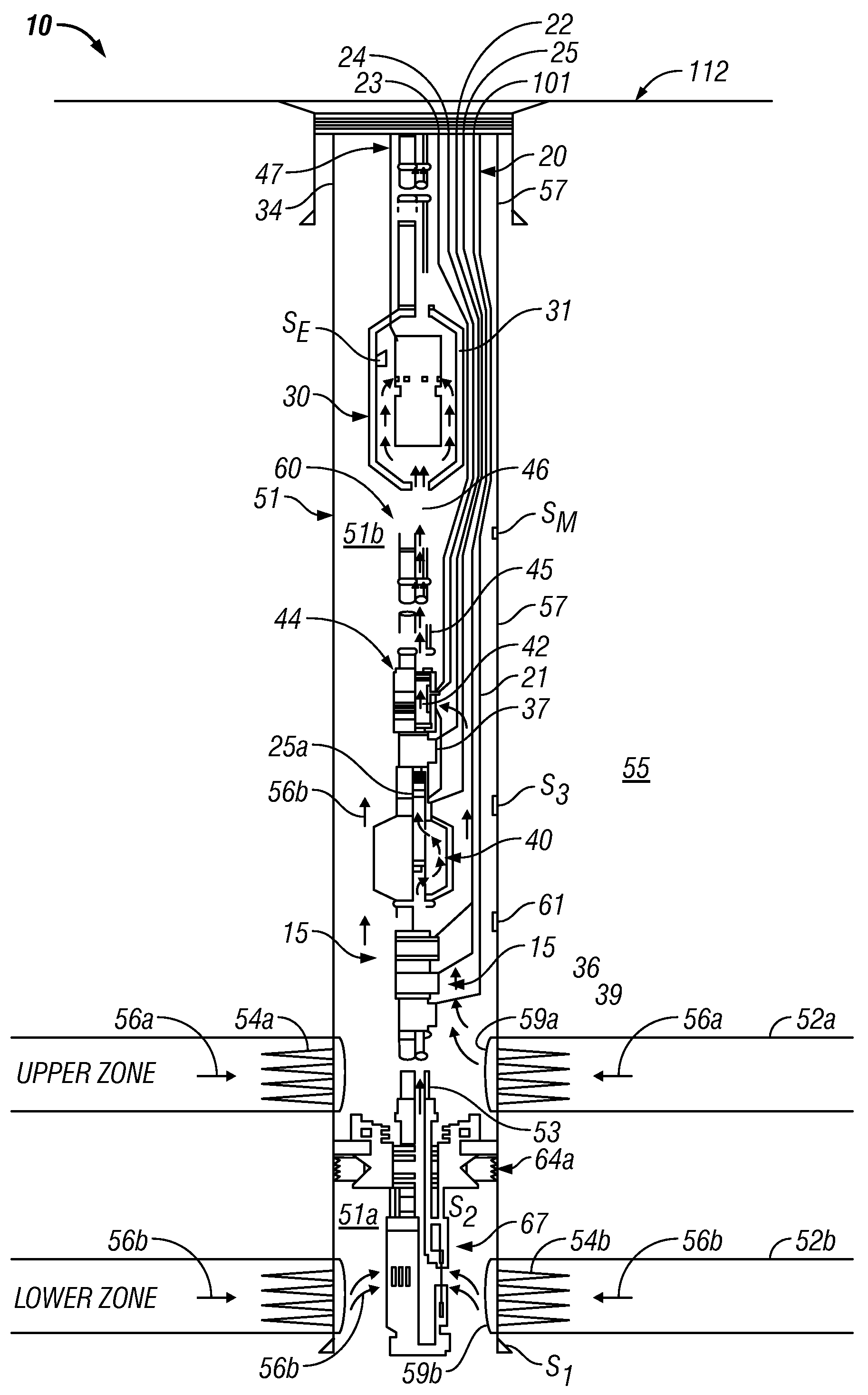
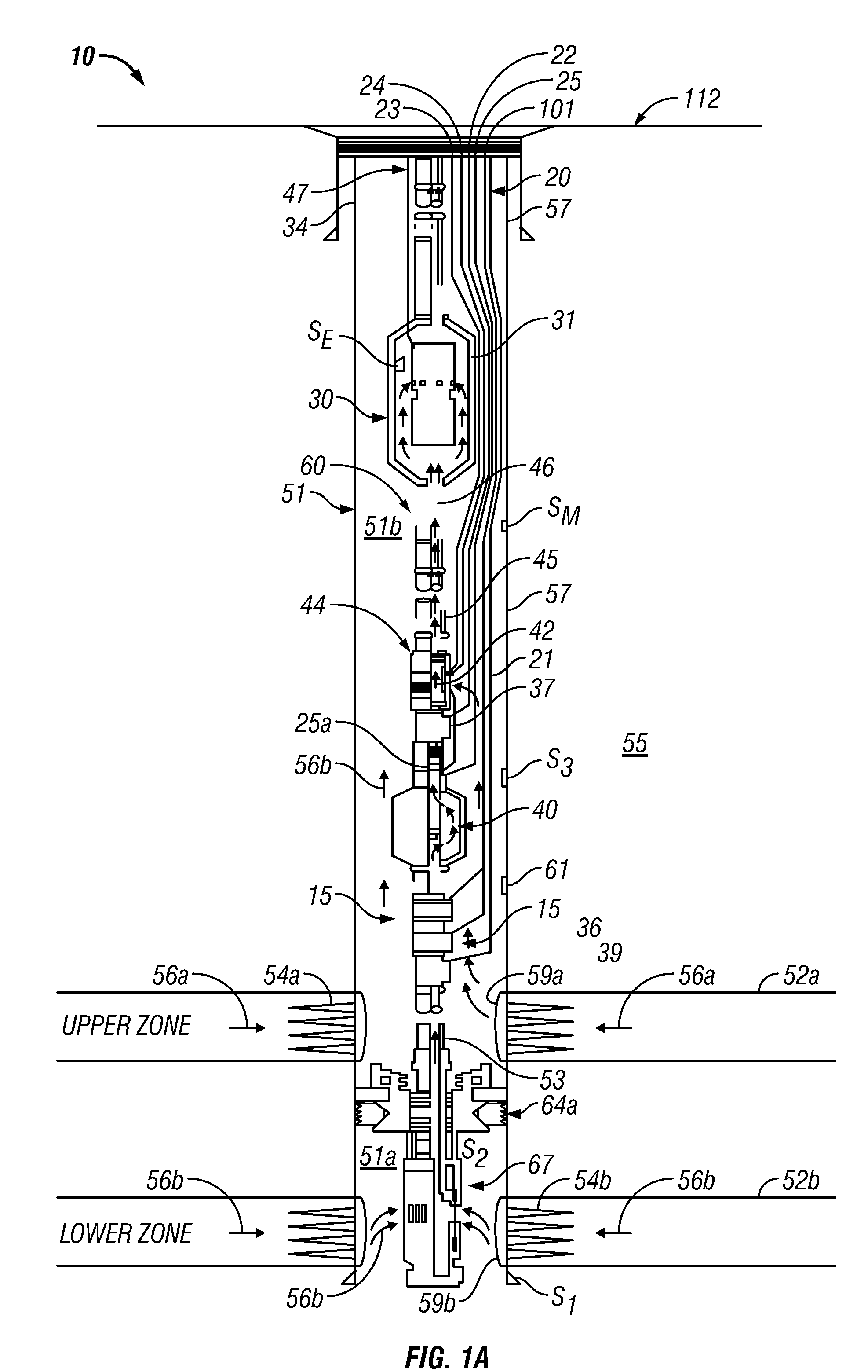
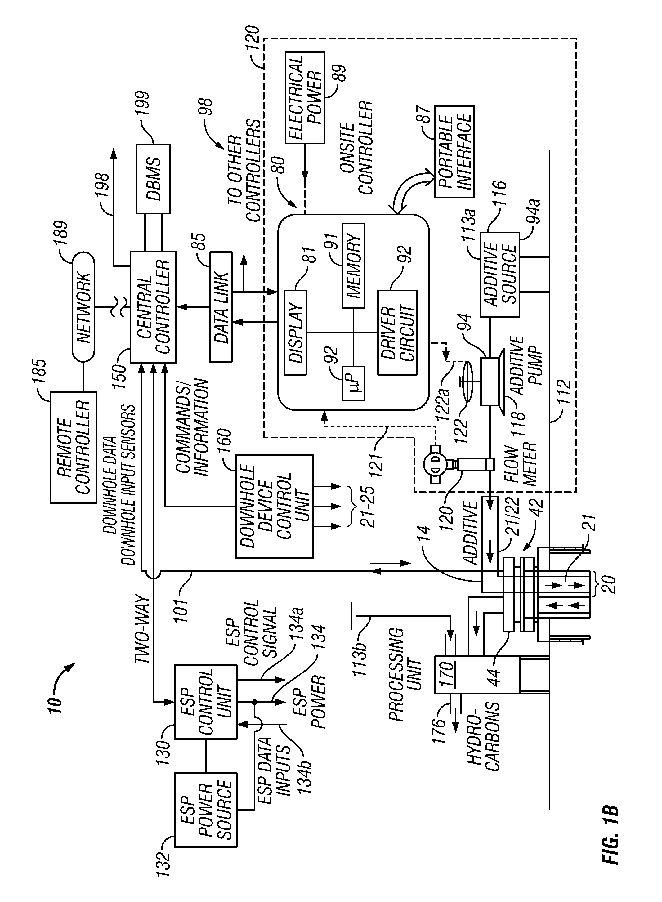
[0017]FIGS. 1A and 1B collectively show a schematic diagram of a production well system 10. FIG. 1A shows a production well 50 that has been configured using exemplary equipment, devices and sensors that may be utilized to implement the concepts and methods described herein. FIG. 1B shows exemplary surface equipment, devices, sensors, controllers, computer programs, models and algorithms that may be utilized to: detect and / or predict an occurrence of a cross flow condition; send appropriate messages and alarms to an operator; determine adjustments to be made or actions to be taken relating to the various operations of the well 50 to mitigate or eliminate negative effects of the potential or actual occurrence of the cross flow condition; automatically control any one or more of the devices or equipment in the system 10; establish a two-way communication with one or more remote locations and / or controllers via appropriate links, including the Internet, wired or wireless links; and aut...


PUM


Abstract

A system and method for managing a production from a wellbore that includes taking measurements relating to one or more selected parameters for each of the production zones over a time period and determining the occurrence of the cross flow in the wellbore using a trend of the one or more of the measurements. The system includes a processor that receives information relating to the measurements made over time relating to the selected parameters, wherein the processor determines or predicts the occurrence of the cross flow from a trend of at least one of the measurements.

Description

CROSS-REFERENCE TO RELATED APPLICATIONS[0001]This application is a continuation-in-part of U.S. patent application Ser. No. 11 / 737,402 filed Apr. 19, 2007.BACKGROUND OF THE DISCLOSURE[0002]1. Field of the Disclosure[0003]This disclosure relates generally to detecting cross flow in production wellbores and for managing production of fluids from the wellbores in response to the detection of the cross flow.[0004]2. Background of the Art[0005]Wellbores are often drilled through formations that include two or more production zones. Such wells are typically completed by placing a casing along the wellbore length and perforating the casing adjacent each such production zone to extract the formation fluids (such as hydrocarbons) into the wellbore. These production zones are sometimes separated from each other by installing a packer between the production zones. Fluid from each production zone entering the wellbore is drawn into a tubing that runs to the surface. Normally, the pressure in th...

Claims


Application Information

Patent Timeline
IPC IPC(8): E21B47/10
CPCE21B47/10E21B43/14E21B43/12
Inventor THIGPEN, BRIAN L.VACHON, GUY P.YERIAZARIAN, GARABEDLEE, JAEDONGCHOK, CHEE M.SANN, CLARKLIU, XIN
Owner BAKER HUGHES INC
Why Eureka
Try Eureka