Methods and compositions for use in cementing in cold environments

a technology of compositions and cementing, applied in the direction of sealing/packing, chemistry apparatus and processes, wellbore/well accessories, etc., can solve the problems of poor wellbore isolation, costly delays, and increased problems

Inactive Publication Date: 2003-09-30
AMERICAN CEMENTING LLC
View PDF60 Cites 197 Cited by
  • Summary
  • Abstract
  • Description
  • Claims
  • Application Information

AI Technical Summary

Problems solved by technology

Cement operations performed in wellbores having relatively cold temperatures, i.e., bottomhole circulating temperatures typically less than about 50.degree. F., may present particular problems, among other things, in obtaining good wellbore isolation.
These problems may be exacerbated in those cases where wellbore and / or formation conditions promote fluid intrusion during or after cement curing, including intrusion of water, gas, or other fluids.
Furthermore, relatively cold temperatures may lead to excessive thickening times, resulting in costly delays while waiting on cement to cure ("WOC").
Under deepwater conditions, relatively cool temperatures promoted by seawater, in some cases coupled with poorly consolidated formations often make the prevention of fluid intrusion during cementing a challenge.
In such cases, relatively cool temperatures (typically less than about 60.degree. F., and more typically, less than about 50.degree. F.) may slow cement curing or hydration, extending the transition time of a cement slurry.
Such cavities or channels may create a permanent flow passage or otherwise compromise the integrity of a cement sheath, such as exists between a pipe string and a formation.
Furthermore, intrusion of a fluid such as water may dilute a cement slurry and thus prevent it from developing sufficient compressive strength.
Fluid migration into a cement is typically more extensive when cement transition times are lengthened because although the cement column in a wellbore has typically built enough gel strength to support itself and to thereby reduce hydrostatic pressure on the surrounding formation, it has not developed sufficient gel strength to prevent fluid intrusion or migration.
Although reduced gel strength, extended transition times, and fluid intrusion during cement curing are problems commonly encountered in deepwater completions, such problems may also be encountered in any wellbore having relatively cool formation temperatures, such as in wellbores drilled in cool or cold climates.
In those cases where formation sands are overpressured by fluids such as gas and / or water, fluid intrusion into the setting cement during the cement transition time may be a particular problem.
In this regard, shallow formations in deepwater wells typically are unconsolidated, making them weak, prone to fracture, and prone to producing relatively high flows of water.
Such a problem may be further exacerbated in those situations in which a relatively lightweight cement slurry is required.
Due to the relatively long transition times of water extended or lightweight cement slurries, there is increased opportunity for fluid intrusion and cement contamination.
Such contamination may result in the loss of formation isolation and / or in casing damage.
Resulting cement job failures may result in many undesirable consequences, such as the need for expensive remedial work, increased rig time, loss of production, and / or loss of the wellbore itself.
In such situations, even where fluid intrusion is not a problem, a cement slurry may not have the opportunity to set and provide needed strength before it freezes.
These cement blends typically contain from about 20% by weight of dry blend ("BWOB") to about 40% BWOB Portland cement, and typically suffer from low compressive strength and high cost.
In some wellbores, gas intrusion may be a particular problem during and after cementing.
This underbalanced pressure may result, for example, in gas channeling to the surface or to another lower pressure permeable zone.
In this regard, thawing of frozen formations may, for example, lead to the creation of a water layer between cement and the formation, which may interfere with the cement-to-formation bond.

Method used


Image

  • Methods and compositions for use in cementing in cold environments
  • Methods and compositions for use in cementing in cold environments
  • Methods and compositions for use in cementing in cold environments

Examples


example 1

In the following example, one embodiment of an aluminum silicate-containing cement slurry was tested and compared to a conventional gypsum-containing cementing system. Characteristics of the conventional gypsum slurry (Slurry #1) and a slurry embodiment employing aluminum silicate (Slurry #2) are presented in Tables 1 and 2. Components of the a slurry systems are listed in Table 1. Slurry properties, testing conditions, and compressive strength information is presented in Table 2.

TABLE 2

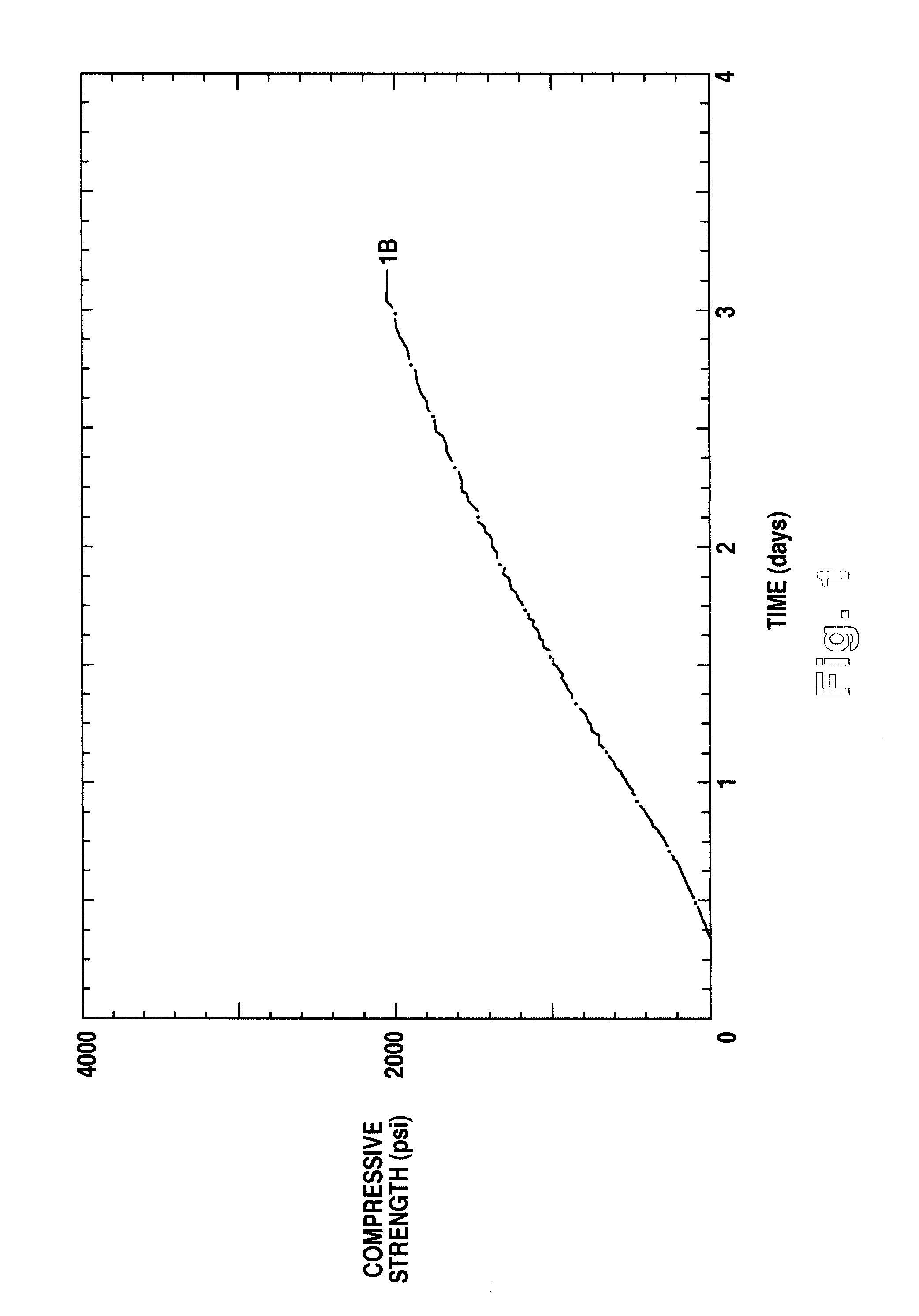
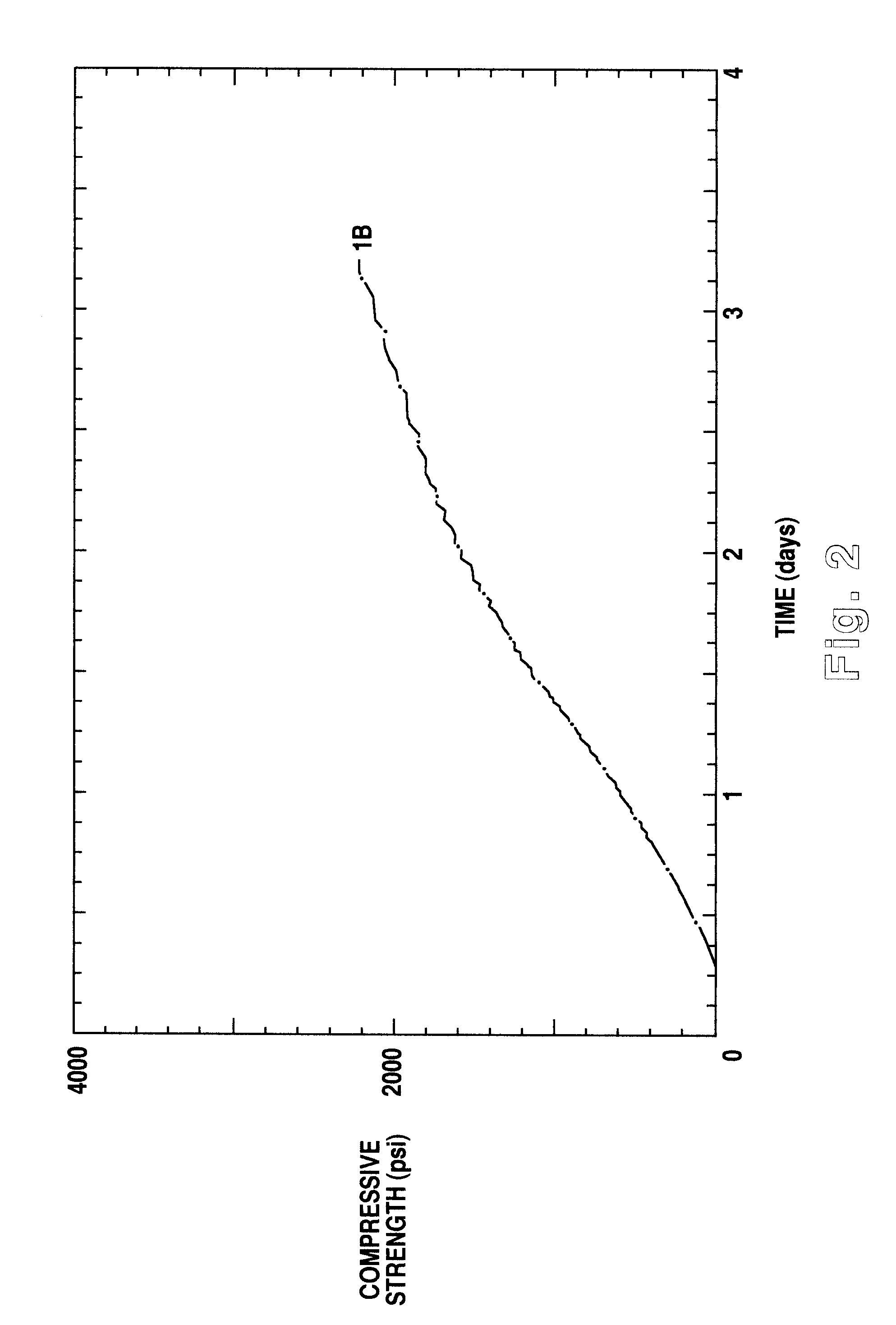
FIG. 1 and FIG. 2 show the development of compressive strength over time (during curing) for Slurry #1 and Slurry #2, respectively. Compressive strength was measured at 3000 psi and 50.degree. F. using an ultrasonic cement analyzer. As can be seen in Table 2, Slurry #2 which includes aluminum silicate according to one of the disclosed embodiments, and methods shows faster development of compressive strength over conventional Slurry #1 which includes gypsum. For example, Slurry #2 develops a compressi...

example 2

In Example 2, a conventional foamed cement slurry (Slurry #1) was compared to one embodiment of a foamed aluminum silicate-containing cement slurry (Slurry #2). Components of Slurry #1 and Slurry #2 are given in Table 3, and slurry properties, testing conditions, and compressive strength information are given in Table 4.

TABLE 4

The results of Example 2 show that foamed aluminum silicate-containing cement Slurry #2 gives a 90% increase in early compressive strength development over conventional foamed cement Slurry #1 while, at the same time, offering a thickening time that is slightly greater than the thickening time of Slurry #1.

examples 3

Aluminum Silicate-Containing Cements For Gas Intrusion Control

Gas flow model curves and thickening time test data were determined for embodiments of the disclosed method using cement slurries prepared for gas intrusion control.

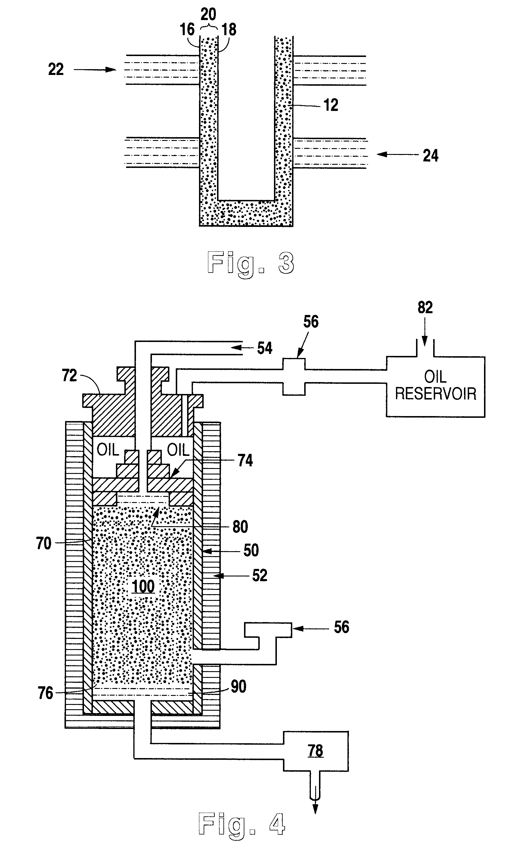
For Examples 3-8, a gas flow model was constructed to simulate a typical well configuration in which a cement slurry is exposed to its own hydrostatic pressure, a pressurized gas formation, and a lower pressure permeable zone, such as the situation illustrated in FIG. 3. A simplified schematic of the gas flow model is shown in FIG. 4. The gas flow model consisted of test cell 50, heating jacket 52, pressurized nitrogen gas source 54, pressure transducers 56, and (not shown) load cells, a linear variable differential transducer ("LVDT"), a data acquisition unit ("DAU"), and a computer. The test cell 50 consisted of test cylinder 70, top head assembly 72, floating piston 74, bottom assembly 76 and back pressure regulator 78.

For each example, the floating piston ...


PUM

PropertyMeasurementUnit
compressive strengthaaaaaaaaaa
densityaaaaaaaaaa
temperatureaaaaaaaaaa

Abstract

Cement compositions for cementing wellbores in cold environments. The cement compositions may include a mixture of a reactive aluminum silicate, aluminum sulfate and hydraulic cement, and may include one or more other additives. The cement compositions may be formulated to have reduced heat of hydration as compared to conventional cements, making them suited for cementing in permafrost environments. The cement slurries may optionally be foamed using a foaming agent and energizing phase.

Description

This invention relates generally to methods and compositions for cementing, and, more specifically to methods and compositions for cementing in cold environments. In particular, this invention relates to methods and compositions for well cementing in permafrost environments utilizing low heat of hydration mixtures of hydraulic cement, aluminum silicate and accelerators.DESCRIPTION OF RELATED ARTCementing is a common technique employed during many phases of wellbore operations. For example, cement may be employed to cement or secure various casing strings and / or liners in a well. In other cases, cementing may be used in remedial operations to repair casing and / or to achieve formation isolation. In still other cases, cementing may be employed during well abandonment. Cement operations performed in wellbores having relatively cold temperatures, i.e., bottomhole circulating temperatures typically less than about 50.degree. F., may present particular problems, among other things, in obta...

Claims


Application Information

Patent Timeline
Patent Type & Authority Patents(United States)
IPC IPC(8): C04B28/04C04B28/00C09K8/42C09K8/46
CPCC04B28/04C09K8/46C04B14/106C04B22/124C04B22/148C04B22/149C04B2111/1018C04B2111/74C04B2111/76C04B2111/766
Inventor GO BONCAN, VIRGILIO C.
Owner AMERICAN CEMENTING LLC
Why Eureka
Try Eureka