
Controlled downhole chemical injection

a chemical injection and controlled technology, applied in the direction of borehole/well accessories, sealing/packing, survey, etc., to achieve the effect of improving the efficiency of artificial lift of petroleum production and improving the flow characteristi

Inactive Publication Date: 2006-01-03
SHELL OIL CO
View PDF135 Cites 199 Cited by
  • Summary
  • Abstract
  • Description
  • Claims
  • Application Information

AI Technical Summary

Benefits of technology

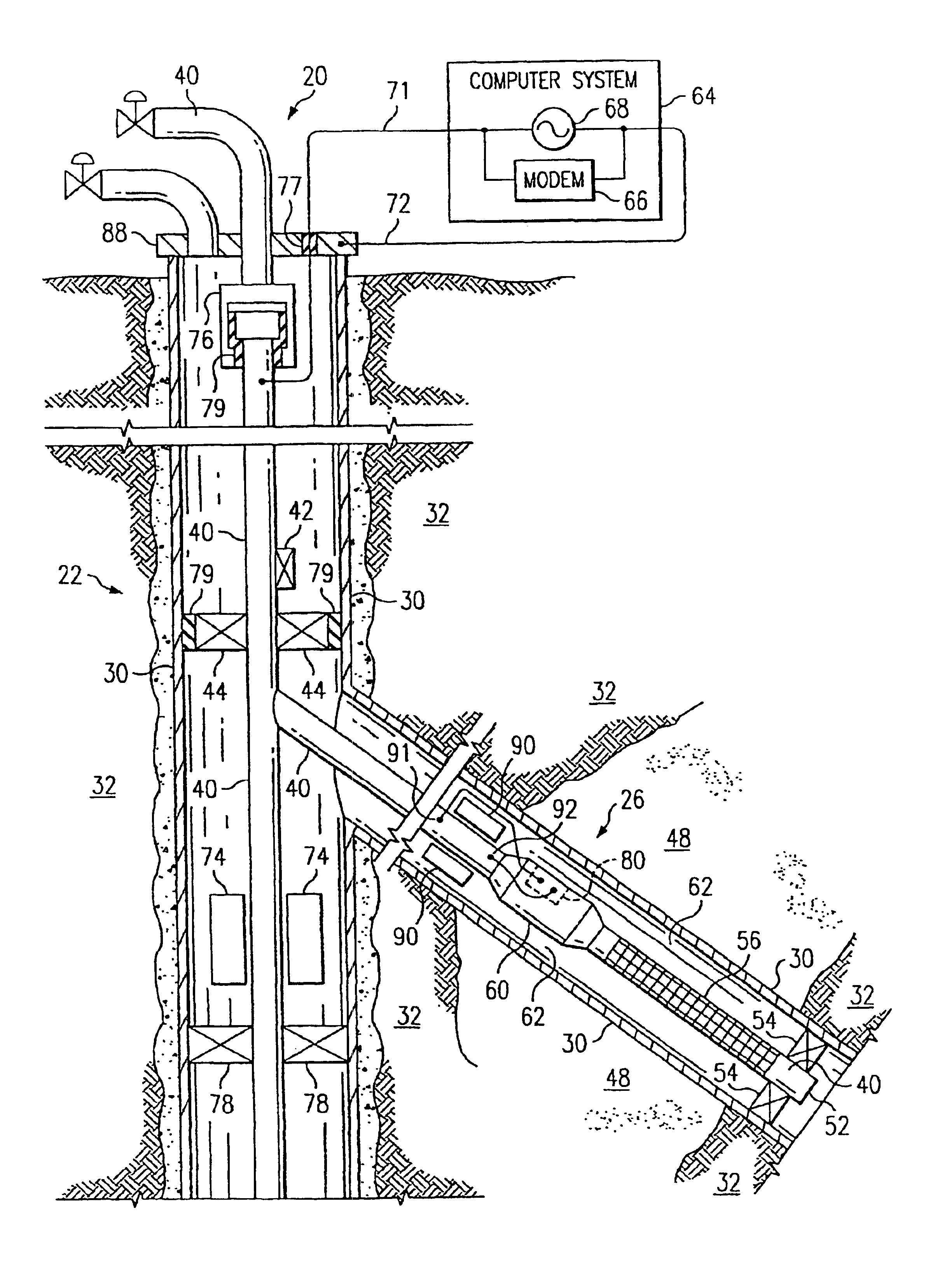
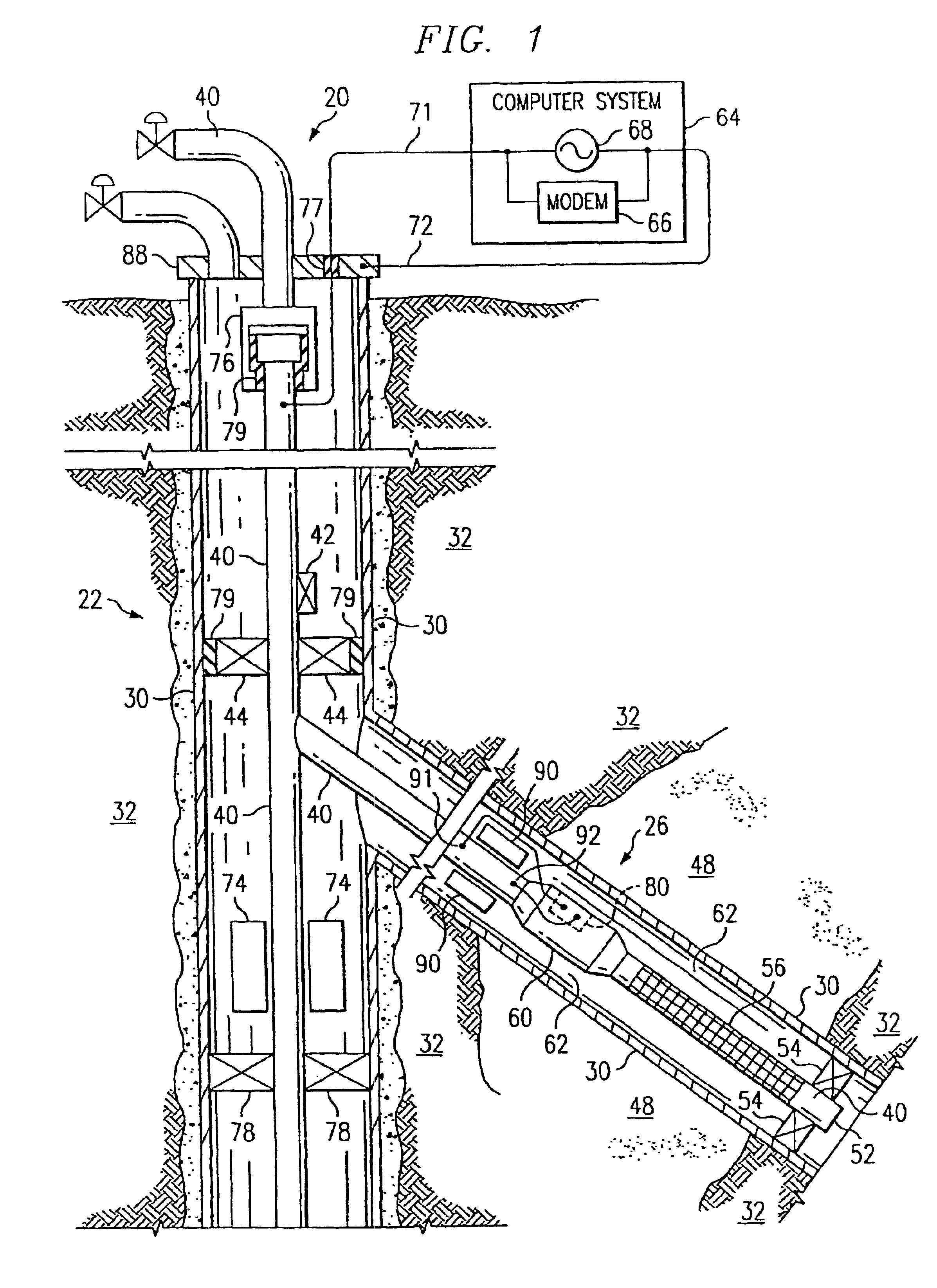
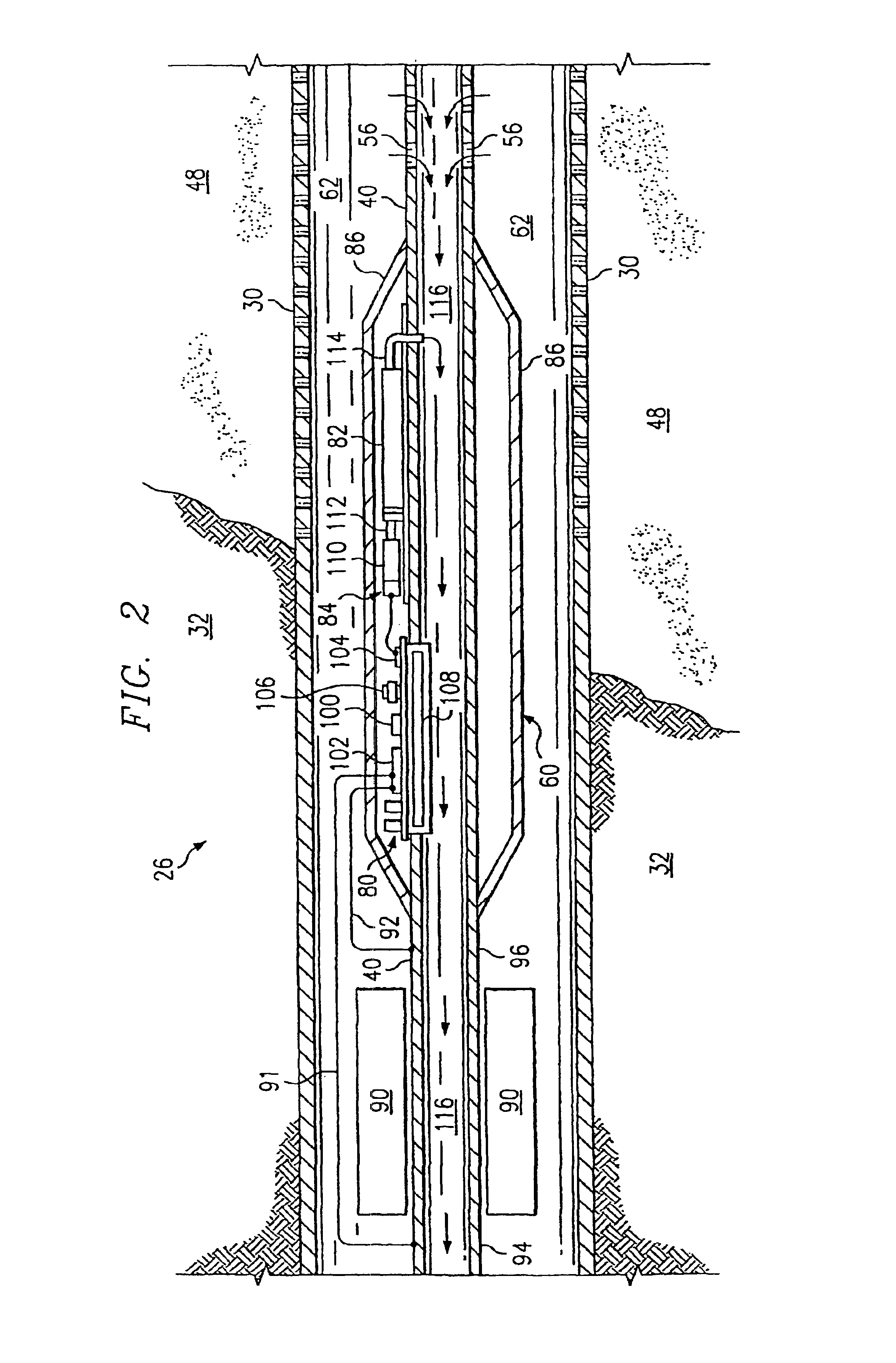
[0018]In accordance with still another aspect of the present invention, a method of producing petroleum products from a petroleum well, is provided. The method comprises the steps of: (i) providing a well casing extending within a wellbore of the well and a production tubing extending within the casing, wherein the casing is electrically connected to the tubing at a downhole location; (ii) providing a downhole chemical injection system for the well comprising an induction choke and an electrically controllable chemical injection device, the induction choke being located downhole about the tubing and / or the casing such that when a time-varying electrical current is transmitted through the tubing and / or the casing, a voltage potential forms between one side of the induction choke and another side of the induction choke, the electrically controllable chemical injection device being located downhole, the injection device being electrically connected to the tubing and / or the casing across the voltage potential formed by the induction choke such that the injection device can be powered by the electrical current, and the injection device being adapted to expel a chemical in response to an electrical signal carried by the electrical current; and (iii) controllably injecting a chemical into a downhole flow stream within the well during production. If the well is a gas-lift well and the chemical comprises a foaming agent, the method may further comprise the step of improving an efficiency of artificial lift of the petroleum productions with the foaming agent. If the chemical comprises a paraffin solvent, the method may further comprise the step of preventing deposition of solids on an interior of the tubing. If the chemical comprises a surfactant, the method may further comprise the step of improving a flow characteristic of the flow stream. If the chemical comprises a corrosion inhibitor, the method may further comprise the step of inhibiting corrosion in said well. If the chemical comprises scale preventers, the method may further comprise the step of reducing scaling in said well.

Problems solved by technology

However, successful application of such techniques requires controlled injection.

Method used


Image

  • Controlled downhole chemical injection
  • Controlled downhole chemical injection
  • Controlled downhole chemical injection

Examples


Embodiment Construction

[0024]Referring now to the drawings, wherein like reference numbers are used herein to designate like elements throughout the various views, a preferred embodiment of the present invention is illustrated and further described, and other possible embodiments of the present invention are described. The figures are not necessarily drawn to scale, and in some instances the drawings have been exaggerated and / or simplified in places for illustrative purposes only. One of ordinary skill in the art will appreciate the many possible applications and variations of the present invention based on the following examples of possible embodiments of the present invention, as well as based on those embodiments illustrated and discussed in the Related Applications, which are incorporated by reference herein to the maximum extent allowed by law.

[0025]As used in the present application, a “piping structure” can be one single pipe, a tubing string, a well casing, a pumping rod, a series of interconnecte...


PUM


Abstract

A petroleum well having a well casing, a production tubing, a source of time-varying current, a downhole chemical injection device, and a downhole induction choke. The casing extends within a wellbore of the well. The tubing extends within the casing. The current source is located at the surface. The current source is electrically connected to, and adapted to output a time-varying current into, the tubing and / or the casing, which act as electrical conductors for providing downhole power and / or communications. The injection device having a communications and control module, a chemical container, and an electrically controllable chemical injector. The communications and control module is electrically connected to the tubing and / or the casing. The chemical injector is electrically connected to the communications and control module, and is in fluid communication with the chemical container. The downhole induction choke is located about a portion of the tubing and / or the casing. The chemical injector is electrically connected to the communications and control module, and is in fluid communication with the chemical container. The downhole induction choke is located about a portion of the tubing and / or the casing. The induction choke is adapted to route part of the electrical current through the communications and control module by creating a voltage potential between one side of the induction choke and another side of the induction choke. The communications and control module is electrically connected across the voltage potential. Also, a method is provided for controllably injecting a chemical into the well downhole, which may be used to: improve lift efficiency with a foaming agent, prevent deposition of solids with a paraffin solvent, improve a flow characteristic of the flow stream with a surfactant, prevent corrosion with a corrosion inhibitor, and / or prevent scaling with scale preventers.

Description

CROSS-REFERENCES TO RELATED APPLICATIONS[0001]This application claims the benefit of the following U.S. Provisional Applications, all of which are hereby incorporated by reference:[0002]COMMONLY OWNED AND PREVIOUSLY FILEDU.S. PROVISIONAL PATENT APPLICATIONST & K #Serial NumberTitleFiling DateTH 159960 / 177,999Toroidal Choke Inductor for Wireless CommunicationJan. 24, 2000and ControlTH 160060 / 178,000Ferromagnetic Choke in WellheadJan. 24, 2000TH 160260 / 178,001Controllable Gas-Lift Well and ValveJan. 24, 2000TH 160360 / 177,883Permanent, Downhole, Wireless, Two-Way TelemetryJan. 24, 2000Backbone Using Redundant Repeater, SpreadSpectrum ArraysTH 166860 / 177,998Petroleum Well Having Downhole Sensors,Jan. 24, 2000Communication, and PowerTH 166960 / 177,997System and Method for Fluid Flow OptimizationJan. 24, 2000TS 618560 / 181,322A Method and Apparatus for the OptimalFeb. 9, 2000Predistortion of an Electromagnetic Signal in aDownhole Communications SystemTH 1599x60 / 186,376Toroidal Choke Inducto...

Claims


Application Information

Patent Timeline
Patent Type & Authority Patents(United States)
IPC IPC(8): E21B43/00E21B17/00E21B34/06E21B34/08E21B34/16E21B37/06E21B41/02E21B43/12E21B43/14E21B47/12H04B5/00
CPCE21B17/003E21B34/066E21B34/08E21B34/16E21B47/122E21B41/02E21B43/123E21B43/14E21B47/12E21B37/06E21B47/13
Inventor STEGEMEIER, GEORGE LEOVINEGAR, HAROLD J.BURNETT, ROBERT REXSAVAGE, WILLIAM MOUNTJOYCARL, JR., FREDERICK GORDONHIRSCH, JOHN MICHELE
Owner SHELL OIL CO
Learn More