A pcb board fixing device for a small mounter

A PCB board and fixing device technology, applied in the direction of electrical components, electrical components, etc., can solve the problems of PCB board installation difficulty, low PCB board applicability, installation dead angle, etc., to improve working stability and service life, and improve fixing stability Sex, to avoid the effect of force deviation

Active Publication Date: 2020-01-07
湖州旭源电气科技有限公司
View PDF8 Cites 0 Cited by
  • Summary
  • Abstract
  • Description
  • Claims
  • Application Information

AI Technical Summary

Problems solved by technology

However, this installation method not only has installation dead angles, but also causes the installation position of the installation seat to not completely cover the entire installation surface, which makes it difficult to install some special-shaped PCB boards and has poor applicability; and the installation seat still has force after it is fixed. The possibility of deviation causes a slight displacement of the PCB board during placement, which affects the placement quality of the small placement machine to the PCB board
Therefore, there are problems of low applicability and poor stability in the fixing method of the existing small placement machine to the PCB board.

Method used


Image

  • A pcb board fixing device for a small mounter
  • A pcb board fixing device for a small mounter
  • A pcb board fixing device for a small mounter

Examples


Embodiment Construction

[0015] The present invention will be further described below in conjunction with the accompanying drawings and embodiments, but not as a basis for limiting the present invention.

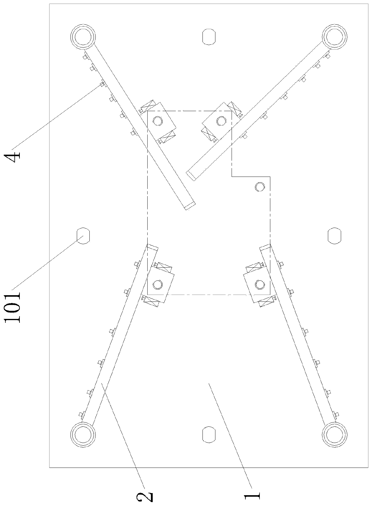
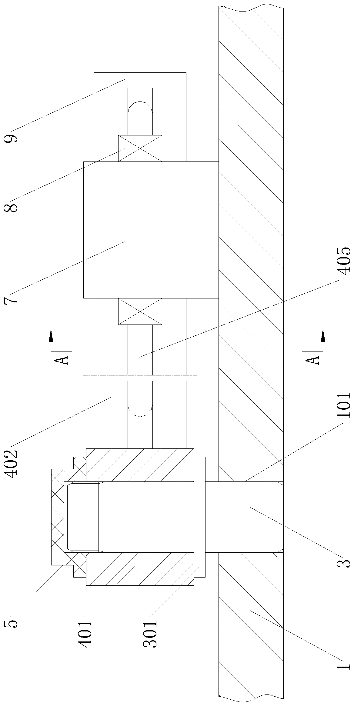
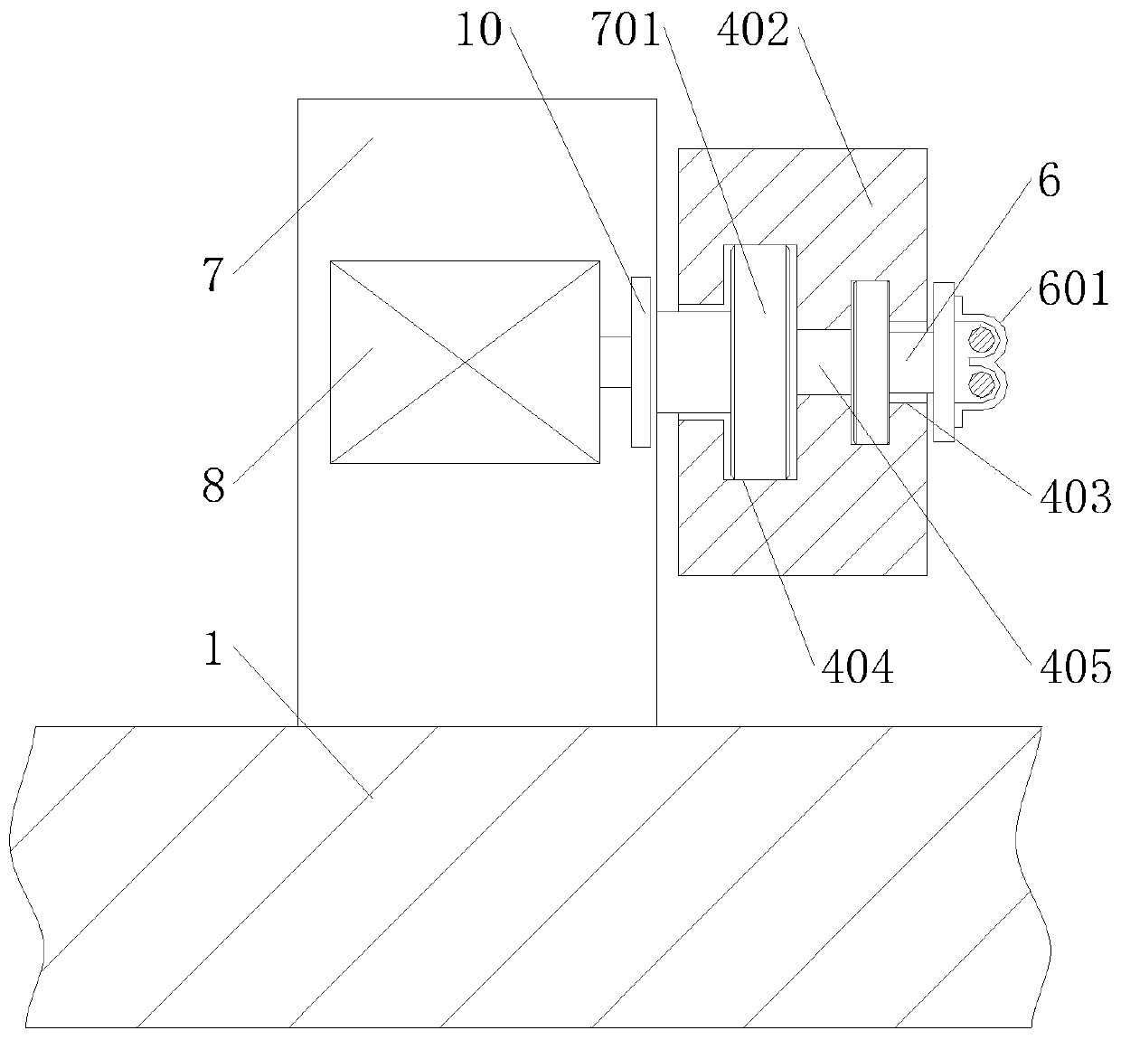
[0016] Example. A PCB board fixing device for a small chip mounter, which consists of figure 1 As shown, the bottom plate 1 is included, and the bottom plate 1 is provided with a plurality of fixed seat groups 2. The fixed seat group 2 includes a fixed shaft 3, the lower end of the fixed shaft 3 is connected to the bottom plate 1, and a rotating arm 4 is connected to the fixed shaft 3 for rotation. The rotating arm 4 includes a rotating cylinder 401. The bottom of the rotating cylinder 401 is provided with a limit plate 301 located outside the fixed shaft 3. The top of the rotating cylinder 401 is provided with a locking cover 5 connected to the fixed shaft 3. The outer wall of the rotating cylinder 401 is One side is provided with an arm body 402, and the two sides of the arm body 402 are respecti...


PUM


Abstract

The invention discloses a PCB board fixing device for a small chip mounter. The device comprises a bottom plate, the bottom plate is provided with a plurality of fixing seat sets, each fixing seat setcomprises a fixed shaft, the lower end of the fixed shaft is connected with the bottom plate, the fixed shaft is rotatably connected with a rotating arm, the rotating arm comprises a rotating cylinder, the bottom of the rotating cylinder is provided with a limiting plate on the outer side of the fixed shaft, the top of the rotating cylinder is provided with a locking cover connected with the fixed shaft, one side of the outer wall of the rotating cylinder is provided with an arm body, a wiring sliding groove and a seat sliding groove are respectively formed in the two sides of the arm body, the wiring sliding groove and the seat sliding groove are communicated with each other through a long strip hole, the wiring sliding groove is provided with a plurality of wire installing seats, a fixing seat is arranged on the sliding groove, a guiding plate cooperating with the seat sliding groove is arranged on the inner side of the fixing seat, electromagnetic locks are arranged at both ends ofthe fixing seat, and a mounting hole is formed in the top of the fixing seat. The device has the advantages of high applicability and good stability.

Description

technical field [0001] The invention relates to a small chip mounter, in particular to a PCB board fixing device for the small chip mounter. Background technique [0002] The placement machine is a device that accurately places surface mount components on the PCB pad by moving the placement head. Compared with the large placement machine, the small placement machine has low production cost, small size, and energy consumption. As an independent processing machine, it is generally placed on the desktop in the office for use due to its low profile. The current small placement machines are limited by cost and volume, and most of them use mechanical mounting structures to fix the PCB board. By distributing a number of mounting screw holes on the mounting surface, the mounting base is fixed on the corresponding position according to the shape of the PCB board. Mounting hole for installation. However, this installation method not only has installation dead angles, but also causes...

Claims


Application Information

Patent Timeline
Patent Type & Authority Patents(China)
IPC IPC(8): H05K13/04
CPCH05K13/046
Inventor 黄雪冰
Owner 湖州旭源电气科技有限公司
Why Eureka
Try Eureka