Gripper drive device and gripper

A driving device and gripper technology, applied in the direction of chuck, manipulator, program-controlled manipulator, etc., can solve the problems of complex fixture system and difficult operation technology level, and achieve the simplified system structure and driving relationship, effective and uniform transmission , The effect of improving drive efficiency and stability

A driving device and gripper technology, applied in the direction of chuck, manipulator, program-controlled manipulator, etc., can solve the problems of complex fixture system and difficult operation technology level, and achieve the simplified system structure and driving relationship, effective and uniform transmission , The effect of improving drive efficiency and stability

CN108568833AInactive Publication Date: 2018-09-25潘杨荣

Image

  • Gripper drive device and gripper
  • Gripper drive device and gripper
  • Gripper drive device and gripper

Examples


Embodiment Construction

[0036] In order to better understand the technical content of the present invention, specific embodiments are given together with the attached drawings for description as follows.

[0037] Aspects of the invention are described in this disclosure with reference to the accompanying drawings, which show a number of illustrated embodiments. Embodiments of the present disclosure are not necessarily intended to include all aspects of the invention. It should be appreciated that the various concepts and embodiments described above, as well as those described in more detail below, can be implemented in any of numerous ways, since the concepts and embodiments disclosed herein are not limited to any implementation. In addition, some aspects of the present disclosure may be used alone or in any suitable combination with other aspects of the present disclosure.

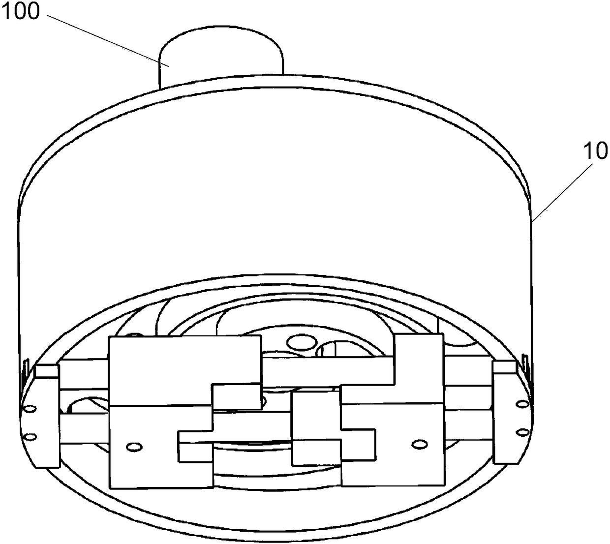
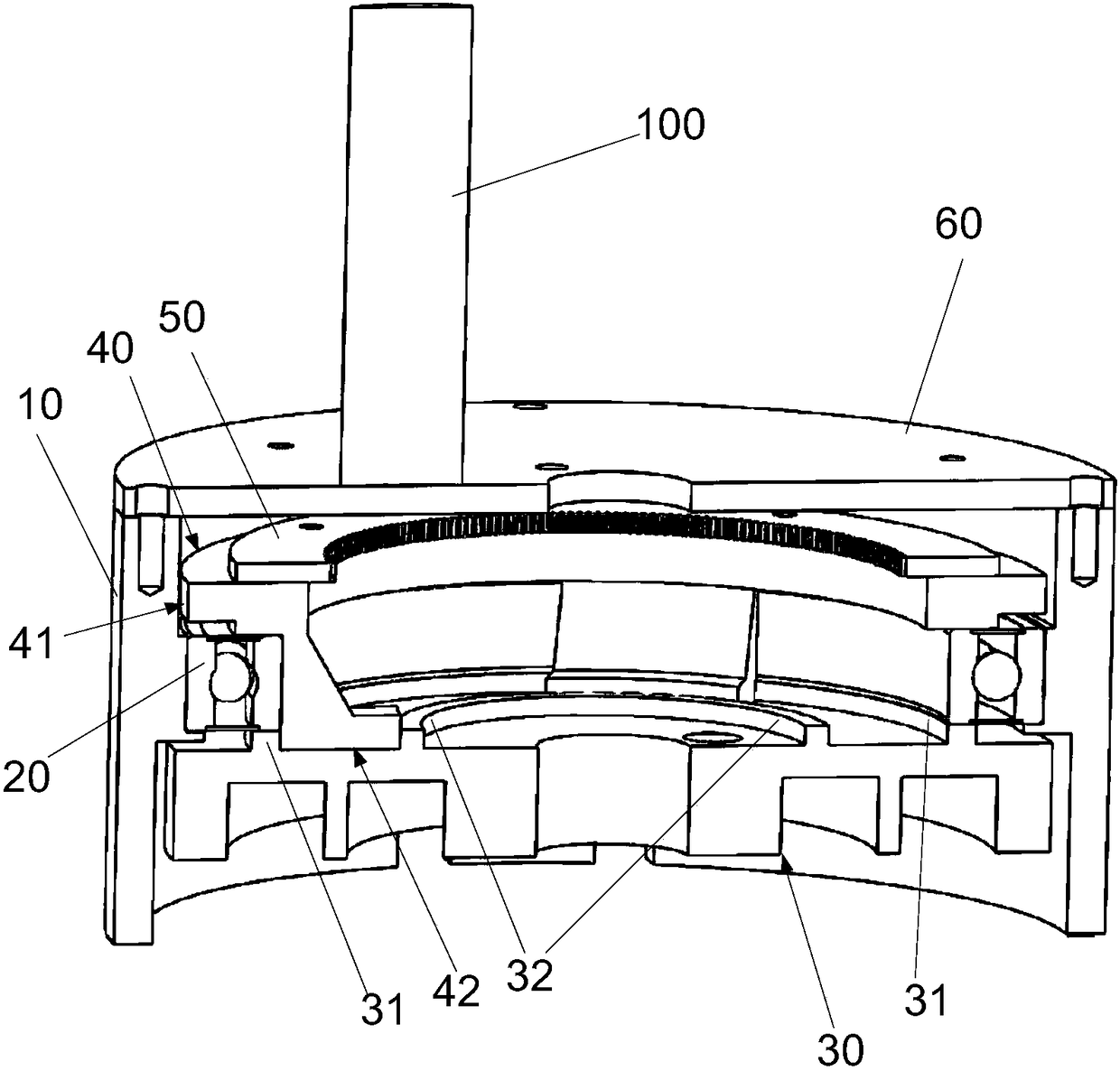
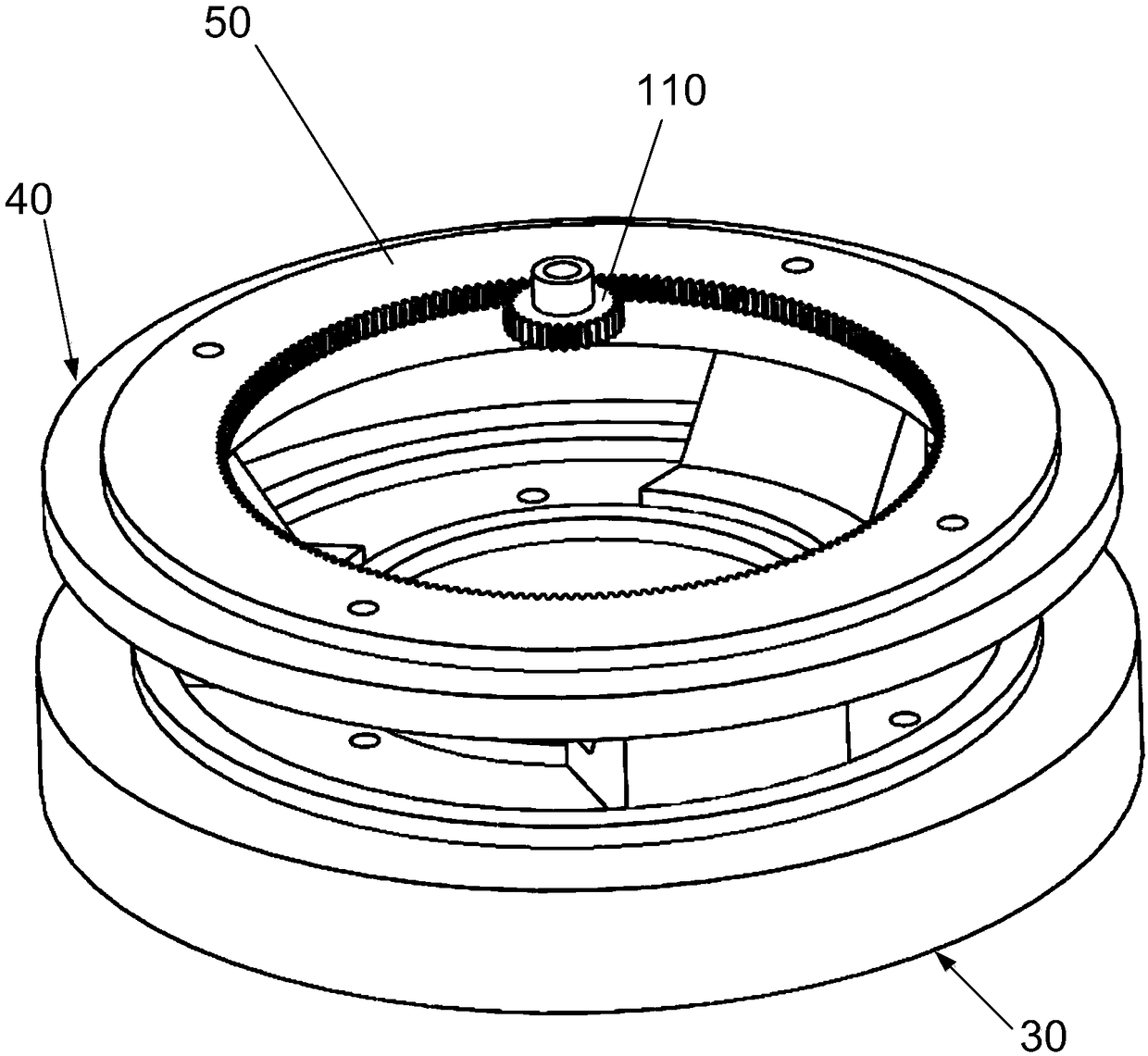
[0038] combine Figure 1-Figure 10 As shown, the gripper driving device disclosed according to the present invention includ...


PUM


Abstract

The invention provides a gripper drive device and a gripper. The gripper drive device comprises a housing as well as a gear, a gear fixed ring, a bearing and a rotary disc which are arranged in the housing, wherein the gear is arranged to receive rotary drive force; the gear fixed ring is fixed with the gear and keeps synchronous rotation with the gear; the bearing supports the gear and the gear fixed ring; the rotary disc is provided with a rotary disc body, and defines a first surface and a second surface of the rotary disc; the first surface is connected to the gear fixed ring, and keeps synchronous rotation with the gear fixed ring; the second surface is equipped with two spiral rails which are symmetrically arranged; the spiral rails provide motion guide and limit for a gripping slideblock of the gripper; and the spiral rails are equal-width grooves which are distributed in the form of an Archimedes screw. The gripper drive device and the gripper can realize precise gripping force distribution and effective gripping.

Description

technical field [0001] The invention relates to the technical field of clamps, in particular to an electric power-driven clamper driving device and a clamper. Background technique [0002] In modern compact manufacturing, robotics, SMT, CNC and other fields, robots and manipulators (arms) are used to replace manual operations to reduce labor intensity and improve operating efficiency and accuracy. In the widespread use of intelligent robots and manipulators (mechanical arms), the function of the pick-up device (fixture, clamping mechanism) is to complete the functions of clamping, grabbing, transferring and placing the workpiece, and it is one of the key components. The current pick-up device is generally driven by hydraulic pressure or air pressure, which is small in size and easy to control, especially for the clamping of small workpieces. However, when the traditional pick-up device is clamped, the torque transmission and distribution of the two gripper parts On the surf...

Claims


Application Information

Patent Timeline
25 Sep 2018
Publication
CN108568833A
IPC
B25J15/00; B25J9/00
CPC
B25J15/00; B25J9/00; B25J9/0009
Inventors
廖猛; 潘杨荣