
Load traction system and measurement method of input end face power of device under test

A technology of input terminal and DUT, which is applied in the direction of electric power measurement by applying the square law characteristic of circuit components, and can solve the problem that power cannot be obtained in real time

Active Publication Date: 2018-10-02
SUZHOU INST OF NANO TECH & NANO BIONICS CHINESE ACEDEMY OF SCI
View PDF9 Cites 8 Cited by
  • Summary
  • Abstract
  • Description
  • Claims
  • Application Information

AI Technical Summary

Problems solved by technology

The power injected into the load from the output end of the DUT can generally be obtained in real time by de-embedding and translating the readings of the power meter to the output end of the DUT. However, the power provided by the system to the input end of the DUT is in the traditional load pulling system is not available in real time

Method used


Image

  • Load traction system and measurement method of input end face power of device under test
  • Load traction system and measurement method of input end face power of device under test
  • Load traction system and measurement method of input end face power of device under test

Examples


Embodiment Construction

[0029] Hereinafter, embodiments of the present invention will be described in detail with reference to the accompanying drawings. This invention may, however, be embodied in many different forms and should not be construed as limited to the specific embodiments set forth herein. Rather, the embodiments are provided to explain the principles of the invention and its practical application, thereby enabling others skilled in the art to understand the invention for various embodiments and with various modifications as are suited to particular intended uses.

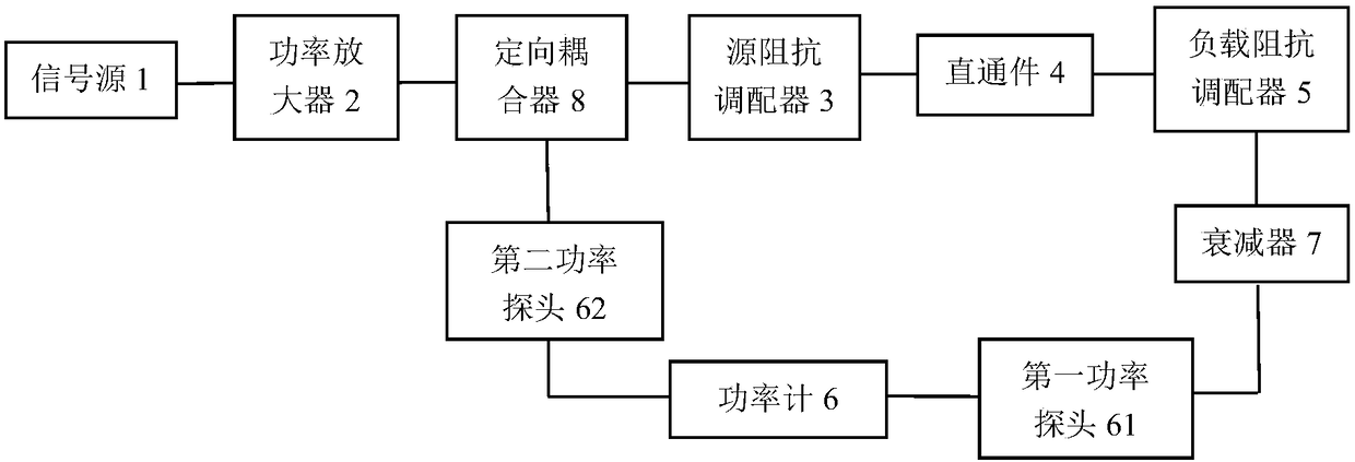
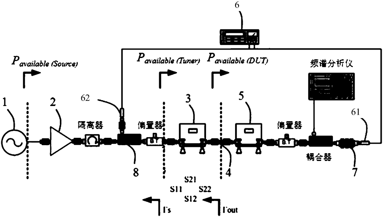
[0030] refer to figure 1 , the load pull system of this embodiment includes a signal source 1 , a power amplifier 2 , a source impedance adjuster 3 , a feed-through 4 , a load impedance adjuster 5 , and a power meter 6 connected to the load impedance adjuster 5 connected in sequence.

[0031] Specifically, the signal source 1 is used to provide a source signal for the entire system, and the power amplifier 2 is used to ampli...


PUM


Abstract

The invention provides a load traction system and a measurement method of the input end face power of a device under test. The method includes the following steps that: the S parameter of a source impedance adapter is obtained through a vector network analyzer; a signal source and a power amplifier are turned on, and the source impedance adapter and a load impedance adapter are placed at a predetermined position; the output power of the signal source is scanned in a predetermined range, and a power value corresponding to the output power is read from a power meter; the power value is transferred to the input end face of the source impedance adapter through de-embedding, so that the power of the input end face of the source impedance adapter can be obtained; and the input end face power ofthe device under test is calculated according to the S parameter and the power of the input end face of the source impedance adapter. With the load traction system and the measurement method of the input end face power of the device under test provided by the invention adopted, the input end face power of the device under test can be obtained in real time.

Description

technical field [0001] The invention belongs to the field of radio frequency microwave measurement, and in particular relates to a method for measuring the input end surface power of a load pulling system and a tested part thereof. Background technique [0002] The purpose of load pull measurement is to provide different impedances and different available powers to the DUT at the input and output ends of the device under test (DUT), and then measure the characteristics of the DUT in these different environments, such as output power, efficiency and other parameters. The load-pull system is an essential system for load-pull measurement of high-power RF microwave power devices. The load-pull system generally consists of a signal source, a power amplifier, an input impedance adjuster, an output impedance adjuster, an attenuator, a power meter and other accessories. composition. [0003] The input and output impedance of most RF microwave power devices are not 50 ohms, and ther...

Claims


Application Information

Patent Timeline
Patent Type & Authority Applications(China)
IPC IPC(8): G01R21/10
CPCG01R21/10
Inventor 余庭
Owner SUZHOU INST OF NANO TECH & NANO BIONICS CHINESE ACEDEMY OF SCI
Learn More