High-end electrical control valve

An electric control valve, high-end technology, applied in the direction of valve details, valve device, valve operation/release device, etc., can solve problems such as accidental power failure, electric shock accident, normal use, etc., and achieve the effect of preventing electric shock accidents

Inactive Publication Date: 2018-10-16
福建广从消防器械有限公司
View PDF8 Cites 2 Cited by
  • Summary
  • Abstract
  • Description
  • Claims
  • Application Information

AI Technical Summary

Problems solved by technology

[0002] Electric control valves are widely used in modern industrial manufacturing. Electric control valves need to be connected to the mains when they are in use, but the power supply pieces in the traditional power supply seat are all connected to the outside. In the end, it will cause electric shock accidents, and there is a great potential safety hazard. At the same time, the traditional electronically controlled valves have poor stability when connected to electricity, and often cause unexpected power failures, which bring great changes to normal use.

Method used


Image

  • High-end electrical control valve
  • High-end electrical control valve

Examples


Embodiment Construction

[0021] All features disclosed in this specification, or steps in all methods or processes disclosed, may be combined in any manner, except for mutually exclusive features and / or steps.

[0022] Any feature disclosed in this specification (including any appended claims, abstract and drawings), unless expressly stated otherwise, may be replaced by alternative features which are equivalent or serve a similar purpose. That is, unless expressly stated otherwise, each feature is one example only of a series of equivalent or similar features.

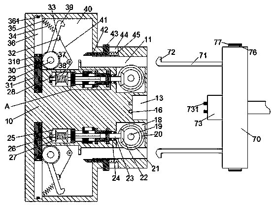
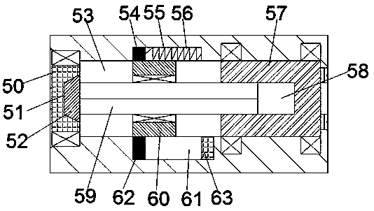
[0023] Such as Figure 1-2As shown, a high-end electric control valve of the device of the present invention includes an electric connection seat 10 and an electric connection head 70 connected with the electric control valve, and the electric connection seat 10 is provided with a rightward recess Groove 13, the inner wall on the left side of the recessed groove 13 is provided with a first conductive groove 16, the right side end surface of t...


PUM


Abstract

The invention discloses a high-end electrical control valve comprising a power connection seat and a power connector connected with the electrical control valve. The power connection seat is providedwith a recessed groove with a rightward groove opening. A first conductive groove is formed in the inner wall of the left side of the recessed groove. The end face of the right side of the power connection seat is symmetrically provided with insertion holes with rightward groove openings, and the insertion holes are located on the upper side and the lower side of the recessed groove. The inner wall, close to the recessed groove, of each insertion hole is internally provided with a first rotation groove in a communicating manner. First toothed wheels are rotationally arranged in the first rotation grooves through first rotation pin shafts. The end face of the front side of each first toothed wheel is provided with a conical tooth ring. First sliding grooves extending left and right are vertically symmetrically arranged in the power connection seat and located on the left side of the first rotation grooves.

Description

technical field [0001] The invention relates to the technical field of electric control valves, in particular to a high-end electric control valve. Background technique [0002] Electric control valves are widely used in modern industrial manufacturing. Electric control valves need to be connected to the mains when they are in use, but the power supply pieces in the traditional power supply seat are all connected to the outside. In the end, it will cause an electric shock accident, which has a great potential safety hazard. At the same time, the traditional electronic control valve has poor stability when it is connected to electricity, and often causes unexpected power failures, which brings great changes to normal use. Contents of the invention [0003] Aiming at the deficiencies of the above technologies, the present invention proposes a high-end electronically controlled valve. [0004] A high-end electric control valve of the device of the present invention include...

Claims


Application Information

Patent Timeline
Patent Type & Authority Applications(China)
IPC IPC(8): F16K31/06
CPCF16K31/0675
Inventor 陈炳华
Owner 福建广从消防器械有限公司
Why Eureka
Try Eureka