
Mobile terminal, control method thereof and computer readable storage medium

A technology of a mobile terminal and a control method, which is applied in the structure of a telephone, a device with a functional camera, a device with a rotatable camera, etc., can solve the problem of occupying a display area, and achieve the effect of increasing the display area and pleasant sound effect

Inactive Publication Date: 2018-10-19
ZTE CORP
View PDF5 Cites 24 Cited by
  • Summary
  • Abstract
  • Description
  • Claims
  • Application Information

AI Technical Summary

Problems solved by technology

[0003] However, the earpiece, front camera and various sensors must be placed on the front of the mobile phone, which is the daily needs of users, but these devices will inevitably occupy a part of the display area when placed on the front of the mobile phone

Method used


Image

  • Mobile terminal, control method thereof and computer readable storage medium
  • Mobile terminal, control method thereof and computer readable storage medium
  • Mobile terminal, control method thereof and computer readable storage medium

Examples


Embodiment 1

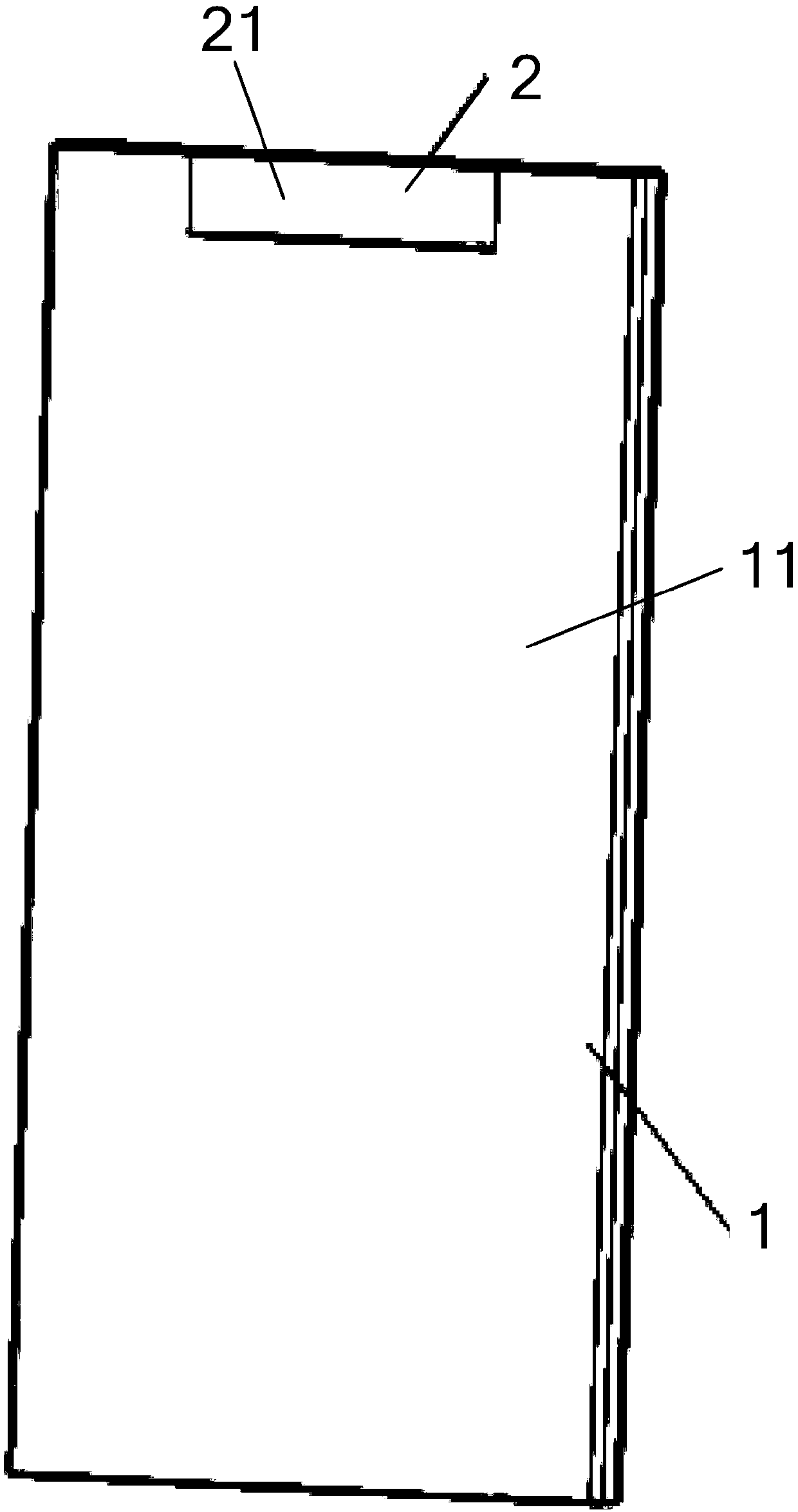
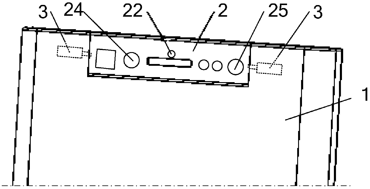
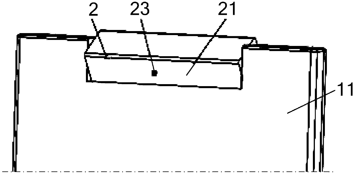
[0036] An embodiment of the present invention provides a mobile terminal, such as Figure 1 to Figure 4 As shown, it includes: a terminal body 1 provided with a main screen 11, the upper end of which is provided with a gap 12 (such as Figure 4 shown); and one side (ie: the front or rear) is provided with a rotating part 2 of the auxiliary screen 21, which can be rotated back and forth and installed at the gap 12, and when the auxiliary screen 21 rotates to the surface where the main screen 11 is located, the auxiliary screen 21 and the auxiliary screen 21 The gaps of the main screen 11 are covered.

[0037] The upper end of the terminal body 1 is provided with a notch 12 that runs through the main screen 11, and the rotating part 2 provided with the auxiliary screen 21 is mounted on the notch 12 so as to be rotatable back and forth. , the auxiliary screen 21 covers the gap of the main screen 11 (that is to say, the main screen 11 and the auxiliary screen 21 form a complete d...

Embodiment 2

[0079] An embodiment of the present invention provides a method for controlling a mobile terminal, such as Figure 8 shown, including:

[0080] S202, acquiring the ambient light, and the relative position of the shooting target and the camera 25;

[0081] S204. Control the drive mechanism 3 to adjust the shooting direction of the camera 25 on the rotating part 2 according to the acquired ambient light and the relative position of the shooting target and the camera 25, and then take pictures.

[0082] During Selfie and post-photographing, the control unit can control the driving mechanism 3 to adjust the shooting direction of the camera 25, so that the shooting target is at a better shooting angle, so as to improve the shooting effect.

[0083] Optionally, as in Figure 9 As shown, the step of controlling the driving mechanism 3 to adjust the shooting direction of the camera 25 on the rotating part 2 according to the obtained ambient light and the relative position of the sho...


PUM


Abstract

The present invention provides a mobile terminal, a control method thereof, and a computer readable storage medium. The mobile terminal includes a terminal body and a rotation component; the terminalbody is provided with a main screen; a gap passing through the main screen is formed in the upper end of the terminal body; one side of the rotation component is provided with an auxiliary screen; the rotation component can be installed at the gap in a manner that the rotation component can rotate backwards and forwards; and when the auxiliary screen rotates to a plane where the main screen is located, the auxiliary screen fully covers the gap of the main screen. According to the mobile terminal, the gap passing through the main screen is formed in the upper end of the terminal body; the rotation component provided with the auxiliary screen can be installed at the gap in a manner that the rotation component can rotate backwards and forwards; when the auxiliary screen rotates to be in a state in which the auxiliary screen faces forwards, the auxiliary screen fully covers the gap, and therefore, a display area can be increased.

Description

technical field [0001] The present invention relates to the technical field of intelligent terminals, in particular to a mobile terminal, a control method for the mobile terminal, and a computer-readable storage medium. Background technique [0002] In order to meet the increasingly stringent consumer demand, major mobile phone manufacturers are pursuing a larger screen-to-body ratio as much as possible to achieve a more perfect display effect. The full screen has become one of the important trends in the development of mobile phones. The full screen literally means that the front of the mobile phone (ie: the front side) is all screens, and the four borders of the mobile phone are designed with no borders, pursuing a screen-to-body ratio close to 100%. But in fact, limited by the current technology, it is only a mobile phone with an ultra-high screen ratio for the time being, and there is no mobile phone that can achieve a 100% front screen ratio. What everyone calls a full...

Claims


Application Information

Patent Timeline
Patent Type & Authority Applications(China)
IPC IPC(8): H04M1/725H04M1/02H04N5/225H04N5/232
CPCH04M1/0264H04M2250/12H04M2250/52H04M2250/20H04M1/72454H04N23/57H04N23/60H04M2250/16H04M1/0266H04N23/53H04N23/58H04N23/67H04N23/698
Inventor 曹丽
Owner ZTE CORP
Learn More