Check patentability & draft patents in minutes with Patsnap Eureka AI!

Defoaming device and defoaming method

A defoaming device and defoaming technology, applied in the direction of chemical instruments and methods, separation methods, maintenance and safety accessories, etc., can solve the problems of cutting fluid leakage, cutting fluid reduction, and deterioration of the working environment, so as to overcome the liquid level rise Fluctuation, liquid level vibration suppression, cost-saving effects

Inactive Publication Date: 2018-10-23
株式会社白山机工
View PDF7 Cites 3 Cited by
  • Summary
  • Abstract
  • Description
  • Claims
  • Application Information

AI Technical Summary

Problems solved by technology

[0014] In addition, there is a problem that a large amount of bubbles leak out of the storage tank, pollute the surroundings of the storage tank, and deteriorate the working environment, or the cutting fluid also leaks out of the storage tank due to bubbles leaking out of the storage tank, and the cutting fluid immediately decreases.

Method used


Image

  • Defoaming device and defoaming method
  • Defoaming device and defoaming method
  • Defoaming device and defoaming method

Examples


Embodiment Construction

[0078] Specific embodiments to which the present invention is applied are described below with reference to the drawings.

[0079] (Embodiment of the present invention)

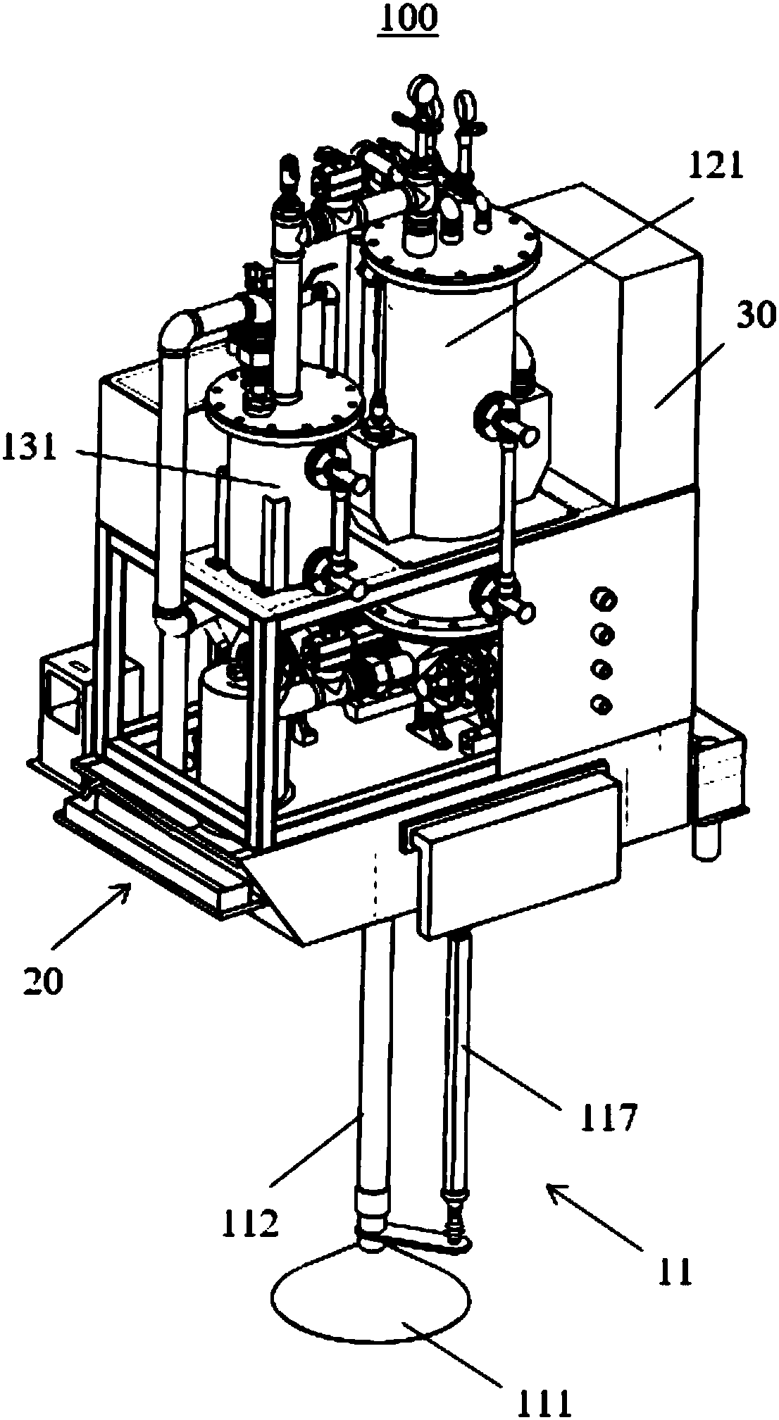
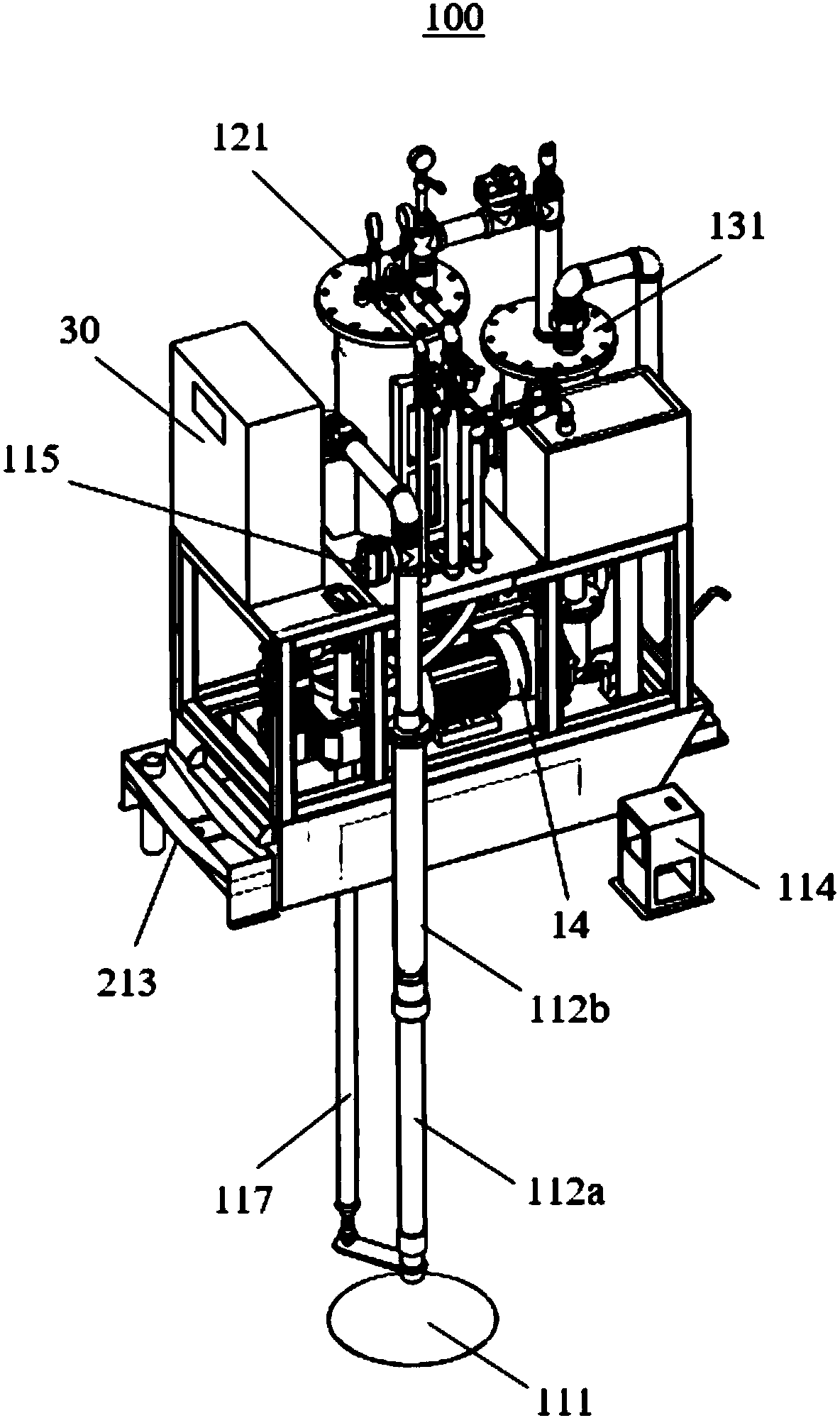
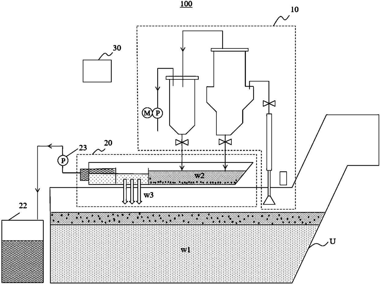
[0080] figure 1 is a three-dimensional view showing the defoaming device according to the embodiment of the present invention figure 1 , figure 2 is a three-dimensional view showing the defoaming device of the above-mentioned embodiment figure 2 , image 3 It is a configuration diagram showing the arrangement of the defoaming device of the above-mentioned embodiment.

[0081] The defoaming device 100 according to the embodiment of the present invention can be installed in a chip removal device that filters cutting fluid discharged from lathes, milling machines, etc. A large number of bubbles, oil or small chips are eliminated, and the mixed oil or small chips are separated from the cutting fluid w1, and the cutting fluid w3 from which the oil has been removed is sent back to the storage tank U of the c...


PUM


Abstract

An object of the present invention is to provide a defoaming device which can properly attract and wipe out a large amount of bubbles generated on a cutting fluid surface, has a simple structure and can be attached to a place which does not constitute an obstacle. The present invention provides a defoaming device 100 for defoaming bubbles contained in a cutting fluid, and is characterized in thatthe defoaming device has a suction portion 11, a defoaming tank portion 12 in which the attracted bubbles are wiped out, a vacuum pump 14 for forming a negative pressure inside the defoaming tank portion 12, and a control portion 30 for attracting and wiping out the bubbles by performing adjusting to allow the pressure in the defoaming tank portion 12 to be the negative pressure value.

Description

technical field [0001] The present invention relates to a defoaming device and defoaming device for removing unnecessary oil such as engine oil and working oil from the cutting fluid by defoaming foam generated in a storage tank for storing cutting fluid (coolant: coolant) used in machine tools such as lathes and milling machines. bubble method. Background technique [0002] Machine tools such as lathes and milling machines are used to supply cutting fluid (coolant) to the processing part where cutting tools such as turning tools (bite) and cutter (cutter) are in contact with the workpiece (workpiece) to perform processing while suppressing heat generation at the processing part The wet type is the mainstream type. Such wet machine tools are often provided with a chip conveyor. The chip removal device separates and discharges chips (unnecessary substances removed from the workpiece) from the cutting fluid mixed with the chips discharged from the machine tool, and at the sa...

Claims


Application Information

Patent Timeline
IPC IPC(8): B01D19/00B23Q11/00
CPCB01D19/00B23Q11/00
Inventor 前清一郎吕振宇
Owner 株式会社白山机工
Features
  • R&D
  • Intellectual Property
  • Life Sciences
  • Materials
  • Tech Scout
  • Unparalleled Data Quality
  • Higher Quality Content
  • 60% Fewer Hallucinations
Learn More