Fan device

An air supply device, non-opposite technology, applied in the direction of the pump device, the components of the pumping device for elastic fluid, the installation of the support structure, etc., can solve the problem of large size, and achieve the effect of suppressing the increase of the interval

Active Publication Date: 2018-11-02
NIDEC CORP
View PDF10 Cites 0 Cited by
  • Summary
  • Abstract
  • Description
  • Claims
  • Application Information

AI Technical Summary

Problems solved by technology

That is, there is a possibility that the device becomes large

Method used


Image

  • Fan device
  • Fan device
  • Fan device

Examples


Embodiment Construction

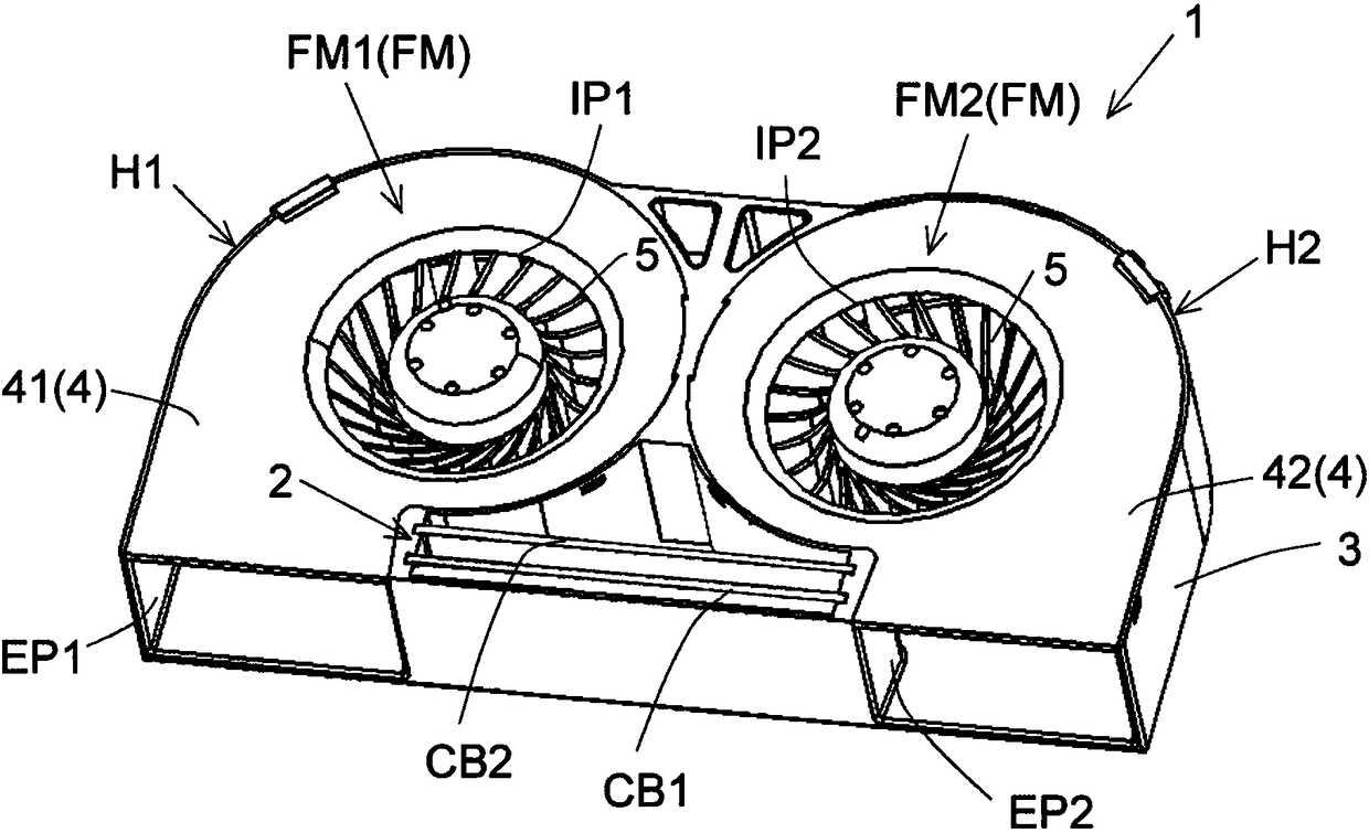
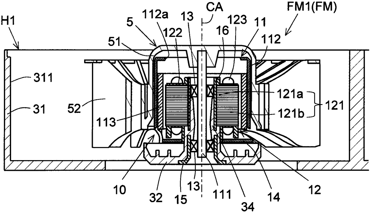
[0042] Hereinafter, exemplary embodiments of the present invention will be described in detail with reference to the drawings. In addition, in this specification, the direction in which the central axis CA which becomes a rotation center when the impeller 5,101 of the fan motor FM which the air blower 1,100 has rotates is extended is made into "axial direction." In addition, the direction perpendicular to the central axis CA is referred to as a "radial direction", and the direction along an arc centered on the central axis CA is referred to as a "circumferential direction".

[0043] In this specification, the axial direction is defined as the up-down direction, and in the axial direction, the direction from the support base 32 supporting the motor unit 10 toward the impeller 5 is defined as the upward direction, and the direction from the impeller 5 toward the support base 32 is defined as the upward direction. Use the expression of up and down directionally. In this specific...


PUM


Abstract

A fan device includes a fan motor and a board storage unit for storing plural circuit boards. The fan motor includes an impeller rotating around a central axis and a wall surface surrounding the impeller outward in a radial direction. The board storage unit is disposed outward from the wall surface in the radial direction. The circuit boards include first and second circuit boards. As viewed froman opposing direction of the first and second circuit boards, the first circuit board has a first opposing area overlapping the second circuit board and a first non-opposing area which does not overlap the second circuit board, and the second circuit board has a second opposing area overlapping the first circuit board and a second non-opposing area which does not overlap the first circuit board. An electronic component or a lead wire is disposed in each of the first and second non-opposing areas.

Description

technical field [0001] The present invention relates to a blower device. Background technique [0002] Japanese Patent Application Laid-Open No. 10-117457 discloses a rotating electrical machine including a terminal box. The terminal box accommodates a board on which a plurality of terminal strips to which lead wires for power supply connection and other lead wires are connected are placed on the outer peripheral portion of the frame. The terminal board to which the above-mentioned other lead wires are connected is covered with the second substrate on which the terminal board to which the display and control lead wires are connected is mounted. The second substrate is supported and fixed on the substrate via spacers. [0003] In the structure disclosed in Japanese Patent Application Laid-Open No. 10-117457, if the size of the terminal plate to which the above-mentioned other lead wires are connected becomes larger in the thickness direction of the substrate, it is necessar...

Claims


Application Information

Patent Timeline
Patent Type & Authority Applications(China)
IPC IPC(8): F04D25/08F04D25/16
CPCH02K11/33F04D25/0613F04D25/0693F04D25/08F04D25/166F04D25/068F04D17/16H05K1/144H05K2201/042H05K2201/10189F04D29/5813H05K1/18H05K7/1427
Inventor 日野典久山崎章基金谷忠之奥野乔也
Owner NIDEC CORP
Why Eureka
Try Eureka