Large stroke actuator based on electromagnetic drive

An electromagnetic drive, electromagnetic drive technology, applied in the direction of transmission, belt/chain/gear, mechanical equipment, etc., can solve the problems that restrict the application and development of actuators, the drive stroke cannot be fully expanded, and the volume cannot be fully reduced. Improve stroke controllability and compatibility, improve compatibility and application range, and achieve the effect of repeated insertion and removal

Inactive Publication Date: 2018-11-02
湖北三江航天红林探控有限公司
View PDF7 Cites 0 Cited by
  • Summary
  • Abstract
  • Description
  • Claims
  • Application Information

AI Technical Summary

Problems solved by technology

[0004] In the prior art, according to the electromagnetic force formula, the output force of the electromagnetic driver is inversely proportional to the driving stroke, that is, the larger the stroke, the smaller the corresponding output force. If a large driving force and a large stroke are required, the coil must be increased. The number of turns makes the structural volume and mass of the electromagnetic driver increase. For example, when the electromagnetic driver needs to have an output force greater than 100N and the stroke is 5mm, the volume of the electromagnetic driver is about The mass is about 2kg. However, when the electromagnetic driver needs to have an output force greater than 100N and the stroke is greater than 20mm, the volume of the electromagnetic driver is about The mass is about 30kg; it can be seen that under the condition of maintaining a certain output force of the electromagnetic driver, a small change in the stroke will have a great impact on the volume and quality of the driver, so that the stroke of the driver cannot be fully expanded, and / or the volume cannot be fully expanded. Sufficiently shrinking, thus restricting the application and development of actuators

Method used


Image

  • Large stroke actuator based on electromagnetic drive
  • Large stroke actuator based on electromagnetic drive
  • Large stroke actuator based on electromagnetic drive

Examples


Embodiment Construction

[0032] In order to make the object, technical solution and advantages of the present invention clearer, the present invention will be further described in detail below in conjunction with the accompanying drawings and embodiments. It should be understood that the specific embodiments described here are only used to explain the present invention, not to limit the present invention.

[0033] In addition, the technical features involved in the various embodiments of the present invention described below can be combined with each other as long as they do not constitute a conflict with each other.

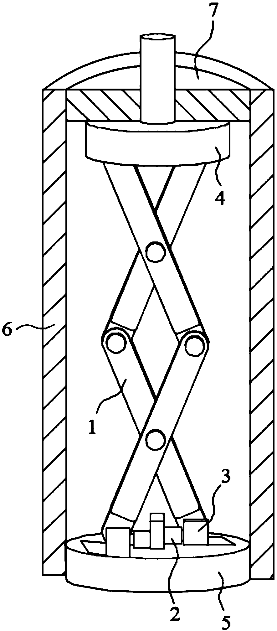
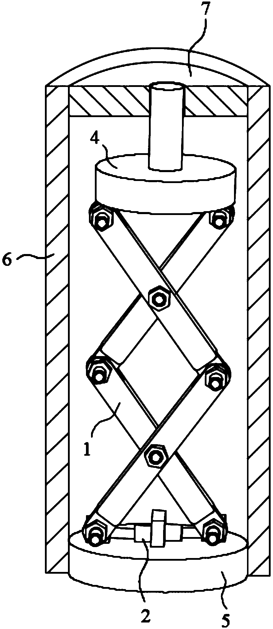
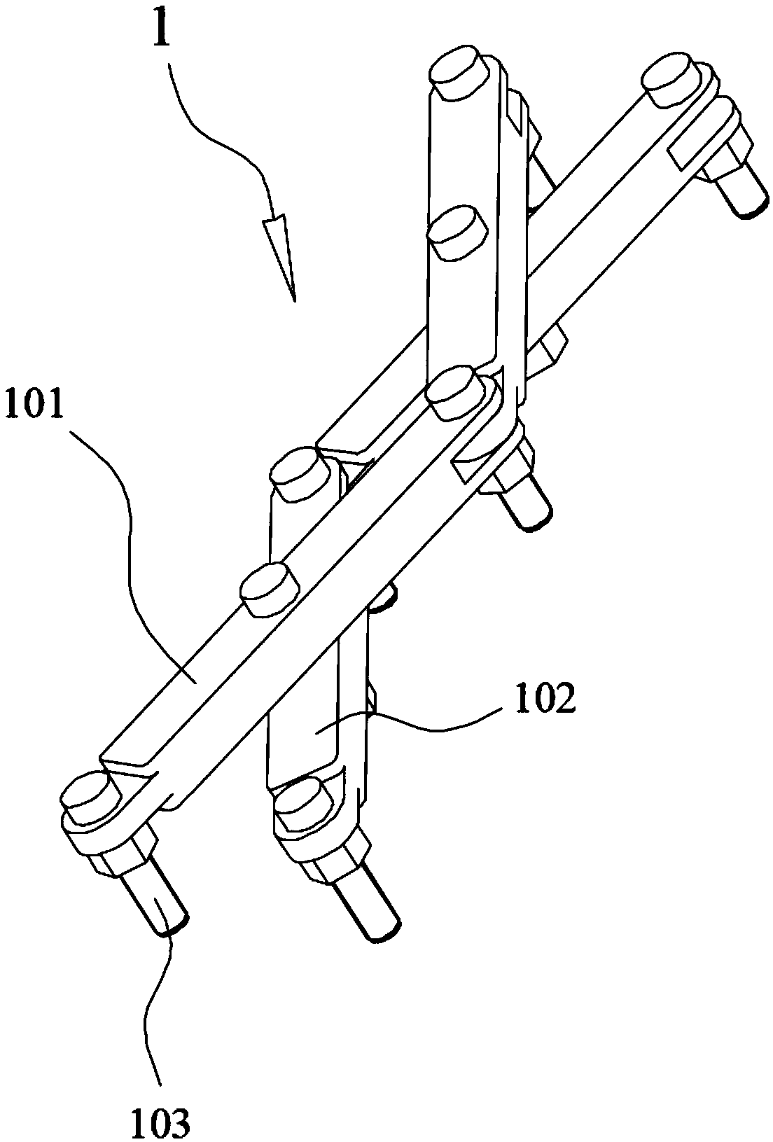
[0034] The structural diagram of the large-stroke actuator based on electromagnetic drive in the preferred embodiment of the present invention is as follows Figure 1~5 As shown in , wherein, the large-stroke actuator in the preferred embodiment includes a housing 6 and a stroke amplification mechanism 1 , an electromagnetic driver 2 , a slider 3 and a base 5 arranged in the housing 6 ....


PUM


Abstract

The invention discloses a large stroke actuator based on electromagnetic drive, and belongs to the technical field of actuator. An electromagnetic driver, sliding blocks and stroke amplification unitsare arranged for cooperation; the electromagnetic driver drives the sliding blocks to move, and movement of the sliding blocks is transformed into relative rotation of two connecting rods of each stroke amplification units; and sliding stroke of the sliding blocks is amplified by at least one stroke amplification unit to be transmitted to a plug-pull piece at one end of the actuator to complete the plug / pull process of the plug-pull piece. The large stroke actuator based on electromagnetic drive is simple in structure and convenient to arrange; the sliding movement of the sliding blocks is effectively amplified by the stroke amplification units; control is simple in the whole process, and controlling accuracy is high; and actuator stroke driving distance changing is effectively achieved by changing the number of the stroke amplification units and / or sliding distance of the sliding blocks, and therefore compatibility of the actuator is greatly improved, large stroke control of the actuator is achieved and excellent popularization and application value is achieved.

Description

technical field [0001] The invention belongs to the related technical field of actuators, and in particular relates to a large-stroke actuator based on electromagnetic drive. Background technique [0002] As a stroke control mechanism, the actuator has been widely used in many fields. With the continuous development of modern industry and science and technology, more requirements are placed on the performance of the actuator, which makes it continue to be small Development in the direction of customization, large stroke, high response speed, etc. [0003] Traditional actuators are mostly based on electromagnetic drive, shape memory alloy drive, fusible alloy drive, or gunpowder drive to complete the actuation process. Among them, electromagnetic drive is a widely used drive form, which provides drive through electromagnetic drive. Force, drive the corresponding components to complete the corresponding stroke, and then complete the working process of the corresponding struct...

Claims


Application Information

Patent Timeline
Patent Type & Authority Applications(China)
IPC IPC(8): F16H21/44
Inventor 李响李军民
Owner 湖北三江航天红林探控有限公司
Why Eureka
Try Eureka