Method for acquiring bidirectional self-lock Hall pulses

A pulse acquisition, two-way self-locking technology, applied in the acquisition field, can solve the problems of magnet demagnetization, hidden danger of product quality, and large sensitivity range of Hall elements, and achieve the effect of ensuring disconnection and easy conduction.

Inactive Publication Date: 2018-11-02
陕西九杰智能仪表有限公司
View PDF7 Cites 2 Cited by
  • Summary
  • Abstract
  • Description
  • Claims
  • Application Information

AI Technical Summary

Problems solved by technology

Among them, the Hall pulse acquisition adopts the magnetic induction method to collect the number of turns of the pointer of the water meter. Because of its signal stability and no jitter, it is more and more popular with users. However, because the Hall element itself adopts the magnetic induction method, there are some problems. The disadvantage is: the sensitivity range of the Hall element itself is very large due to the great change of the magnetic field strength, and the requirements for the accuracy of the magnet and the change of the installation position are very strict, so if the conduction and disconnection are judged according to the magnitude of the magnetic field strength, in There will be many problems in the batch application of the product. The traditional Hall pulse signal acquisition is to use the strength of the magnetic field to judge the conduction and disconnection of the Hall element, because the position of the Hall is limited. The horizontal distance of the water meter is only about 10 mm, and the vertical distance is only about 11 mm. It is necessary to ensure that the magnet can be turned on when it is directly below the Hall element, and it can be disconnected when it is far away from the Hall element. Choose the Gauss value of the magnet. The difficulty is increased, and the sensitivity range of the Hall element is very large. What's more frightening is that the error of the installation position cannot be greater than 1 mm, and the magnet will demagnetize during use, which will bring hidden dangers to the quality of the product, so it is stable The use of Hall elements with good performance on water meters has been affected. Therefore, we propose a two-way self-locking Hall pulse acquisition method

Method used


Image

  • Method for acquiring bidirectional self-lock Hall pulses

Examples


Embodiment Construction

[0011] The following will clearly and completely describe the technical solutions in the embodiments of the present invention with reference to the accompanying drawings in the embodiments of the present invention. Obviously, the described embodiments are only some, not all, embodiments of the present invention. Based on the embodiments of the present invention, all other embodiments obtained by persons of ordinary skill in the art without making creative efforts belong to the protection scope of the present invention.

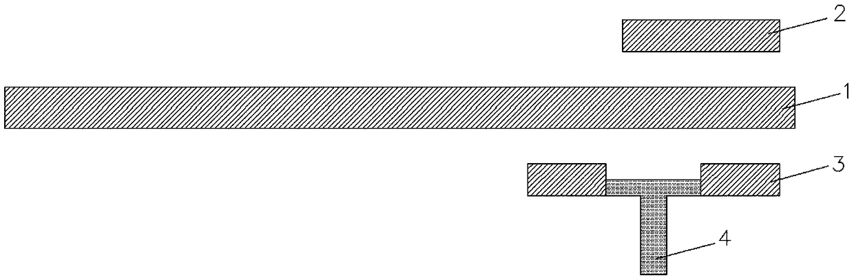
[0012] see figure 1 , the present invention provides a technical solution: a two-way self-locking Hall pulse acquisition method, including an N-pole Hall element 1, a glass 2, a magnet 3 and a connector 4, and the N-pole Hall element 1 does not use a bipolar The sensitivity is 3.0MT, and the average power consumption is 2 microamperes. When the N-pole Hall element 1 is under the N-pole upward magnet 3, its N-pole Hall element 1 is turned on. When the N-pole Ha...


PUM


Abstract

The invention discloses a method for acquiring bidirectional self-lock Hall pulses. The method is implemented by an N-pole Hall element, glass, magnets and a connecting piece. The N-pole Hall elementis not a bipolar Hall element, the sensitivity of the N-pole Hall element is 3.0 MT, the average power consumption of the N-pole Hall element is at the micro-ampere level, and the N-pole Hall elementis conducted when the magnet with an upward N pole is positioned below the N-pole Hall element, and can be disconnected when the magnet with an upward S pole is positioned below the N-pole Hall element. The method has the advantages problems can be completely solved by the aid of a fundamental principle that the conduction and disconnection of the Hall element are judged according to the polarityof the magnets instead of the magnitude of magnetic fields of the magnets; the N-pole Hall element, the glass, the magnets and the connecting piece are easy to mount, the method is suitable for batchproduction, and reverse flowing water of water meters can be judged by the aid of the method.

Description

technical field [0001] The invention relates to a collection method, in particular to a bidirectional self-locking Hall pulse collection method. Background technique [0002] At present, there are generally three ways to collect water consumption of water meters: ultrasonic, photoelectric direct reading, reed switch pulse collection, and Hall pulse collection. Among them, the Hall pulse acquisition adopts the magnetic induction method to collect the number of turns of the pointer of the water meter. Because of its signal stability and no jitter, it is more and more popular with users. However, because the Hall element itself adopts the magnetic induction method, there are some problems. The disadvantage is: the sensitivity range of the Hall element itself is very large due to the great change of the magnetic field strength, and the requirements for the accuracy of the magnet and the change of the installation position are very strict, so if the conduction and disconnection a...

Claims


Application Information

Patent Timeline
Patent Type & Authority Applications(China)
IPC IPC(8): G01F15/07
CPCG01F15/075
Inventor 毛加兴刘先余冯爱铭
Owner 陕西九杰智能仪表有限公司
Why Eureka
Try Eureka