Supercharge Your Innovation With Domain-Expert AI Agents!

Buckle structure and automobile lamp

A technology of a buckle structure and a car lamp, which is applied in the directions of motor vehicles, road vehicles, lighting devices, etc., can solve the problems of low installation efficiency and cannot guarantee effective fixing, and achieve the effect of high installation efficiency.

Pending Publication Date: 2018-11-13
HASCO VISION TECHNOLOGY CO LTD
View PDF0 Cites 4 Cited by
  • Summary
  • Abstract
  • Description
  • Claims
  • Application Information

AI Technical Summary

Problems solved by technology

[0005] The purpose of the present invention is to provide a buckle structure to solve the technical problems in the prior art that the effective fixation in the assembly process cannot be guaranteed when multiple parts are installed and the installation efficiency is low

Method used


Image

  • Buckle structure and automobile lamp
  • Buckle structure and automobile lamp
  • Buckle structure and automobile lamp

Examples


Embodiment 1

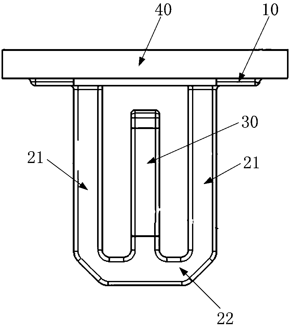
[0037] like Figure 1-Figure 6 As shown, the buckle structure provided by the embodiment of the present invention includes:

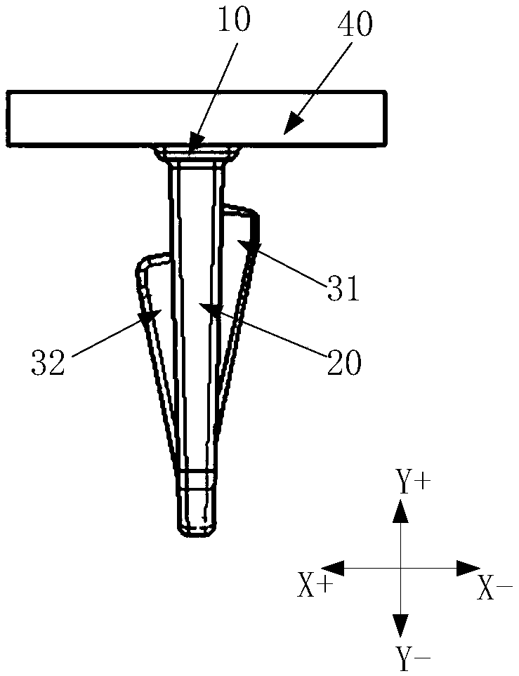
[0038] The buckle structure provided by the embodiment of the present invention includes: a fixed arm 20 and an elastic cantilever 30 , the fixed arm 20 is used for connecting with the first component 40 , the elastic cantilever 30 is connected with the fixed arm 20 , the opposite side edges of the elastic cantilever 30 are A first pressure tongue 31 and a second pressure tongue 32 are respectively provided in the vertical direction, and the distance between the first pressure tongue 31 and the fixed end of the fixed arm 20 is smaller than the distance between the second pressure tongue 32 and the fixed end of the fixed arm 20 . distance.

[0039] In a specific implementation of this embodiment, the fixed end of the fixed arm 20 may be directly connected to the first component 40, or, in another specific implementation of this embodiment, the fixed end...

Embodiment 2

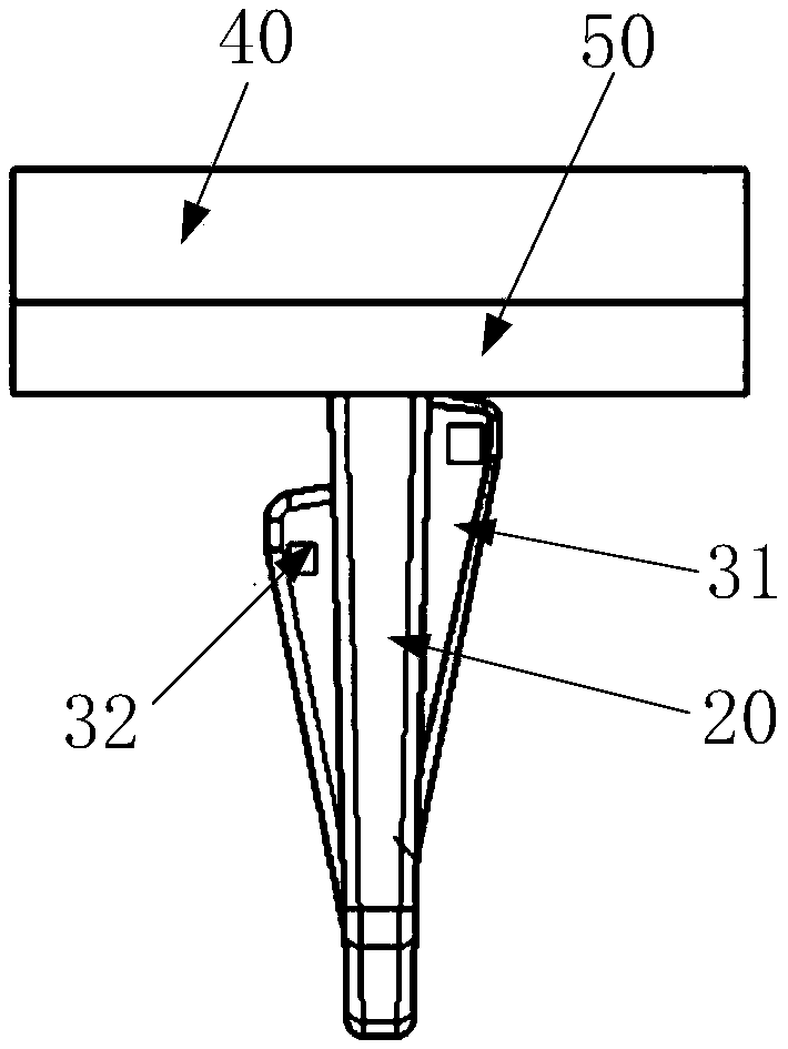
[0063] The second embodiment provides a vehicle lamp, including: a first part 40 , a second part 50 and the buckle structure provided in the first embodiment above. The mounting plate 10 of the buckle structure is connected to the first part 40 , and the second part 50 The second component 50 is located between the first pressing tongue 31 of the buckle structure and the first component 40 by connecting with the first component 40 through the buckle structure.

[0064] Further, the vehicle lamp further includes a third part 60 , and the third part 60 is located between the second part 50 and the second pressing tongue 32 of the buckle structure.

[0065] The first part 40 , the second part 50 and the third part 60 are all parts in the lamp, and the first part 40 , the second part 50 and the third part 60 are connected by a snap structure.

[0066] In specific implementation, in figure 2 In the direction of the coordinate system shown, the thickness of the second part 50 on t...


PUM


Abstract

The invention provides a buckle structure and an automobile lamp, relates to the technical field of automobile lamps, and aims at solving the problems that when a buckle is used for installing a plurality of components, effective fixing in the assembling process cannot be guaranteed, and the installing efficiency is low. The buckle structure comprises a fixing arm and an elastic cantilever, the fixing end of the fixing arm is used for being connected with a first component, the elastic cantilever is connected with the fixing arm, a first pressing tongue and a second pressing tongue are arranged on the two opposite sides of the elastic cantilever in the vertical direction correspondingly, and the distance between the first pressing tongue and the fixing end of the fixing arm is smaller thanthe distance between the second pressing tongue and the fixing end of the fixing arm. The fixing end of a fixing plate is connected with the first component, and after a second component sleeves thefirst pressing tongue, the second component abuts against the first component through the first pressing tongue. After the second component sleeves the second pressing tongue, the second component abuts against the second component through the second pressing tongue. When a third component is installed, the second component is fixed through the first pressing tongue. Accordingly, in the assemblingprocess, the fixing effect is good, and the assembling efficiency is high.

Description

technical field [0001] The present invention relates to the technical field of vehicle lamps, in particular to a buckle structure and a vehicle lamp. Background technique [0002] At present, with the continuous advancement of technology in the field of automotive lights, the functional integration of automotive lights is getting higher and higher, the structure is more and more complex, and the space inside the automotive lights is becoming more and more limited. [0003] In car lights, the use of snap assembly between parts is an effective way to save space, simplify the assembly process, and reduce parts compared to using screws to install. However, because the existing buckle can only deform in the same direction, it is impossible to guarantee the effective fixation during the assembly process when installing multiple parts, and it is necessary to wait until the two parts are all installed in place before the fixation can be completed. [0004] Therefore, when using the...

Claims


Application Information

Patent Timeline
IPC IPC(8): F21V17/16F21W107/10
CPCF21V17/164F21W2107/10
Inventor 李辉仇智平
Owner HASCO VISION TECHNOLOGY CO LTD
Features
  • R&D
  • Intellectual Property
  • Life Sciences
  • Materials
  • Tech Scout
  • Unparalleled Data Quality
  • Higher Quality Content
  • 60% Fewer Hallucinations
Learn More