Optical cable splice box

An optical cable splice box and optical cable technology, applied in the field of communication, achieves the effects of excellent ventilation performance, avoiding loosening of optical cable joints, and low manufacturing cost

Inactive Publication Date: 2018-11-13
U COM TELECOM EQUIP CO LTD
View PDF5 Cites 2 Cited by
  • Summary
  • Abstract
  • Description
  • Claims
  • Application Information

AI Technical Summary

Problems solved by technology

[0006] The inventor found through painstaking research that sudden changes in temperature are one of the main reasons for the loosening of optical cable joints. Therefore, how to influence the impact of sudden temperature changes on optical cable splice boxes is an important subject of research, and by increasing ventilation, it can be To solve the above problems to the greatest extent is not limited to theoretical constraints. When the ambient temperature changes suddenly, the circulation and exchange of gas will occur due to the "unsealed state" of the optical cable splice box, so that the temperature difference between the inside and outside of the splice box will not be too large, so Reduce the phenomenon of uneven expansion or contraction caused by different temperature differences, and avoid the problem of loosening of optical cables at the joints

Method used


Image

  • Optical cable splice box
  • Optical cable splice box
  • Optical cable splice box

Examples


Embodiment Construction

[0019] In order to make the technical means, creative features, goals and effects achieved by the present invention easy to understand, the present invention will be further described below in conjunction with specific embodiments.

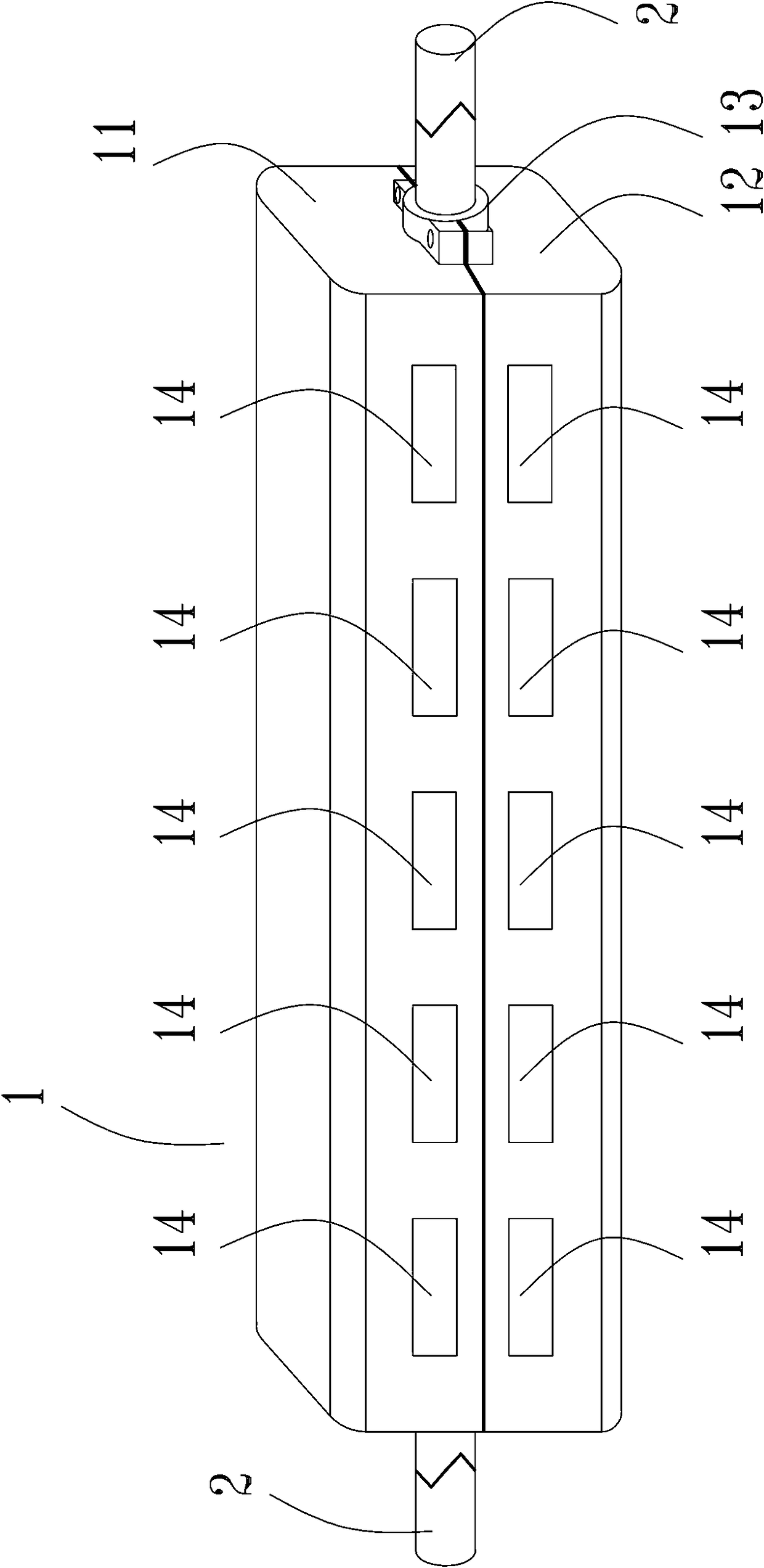
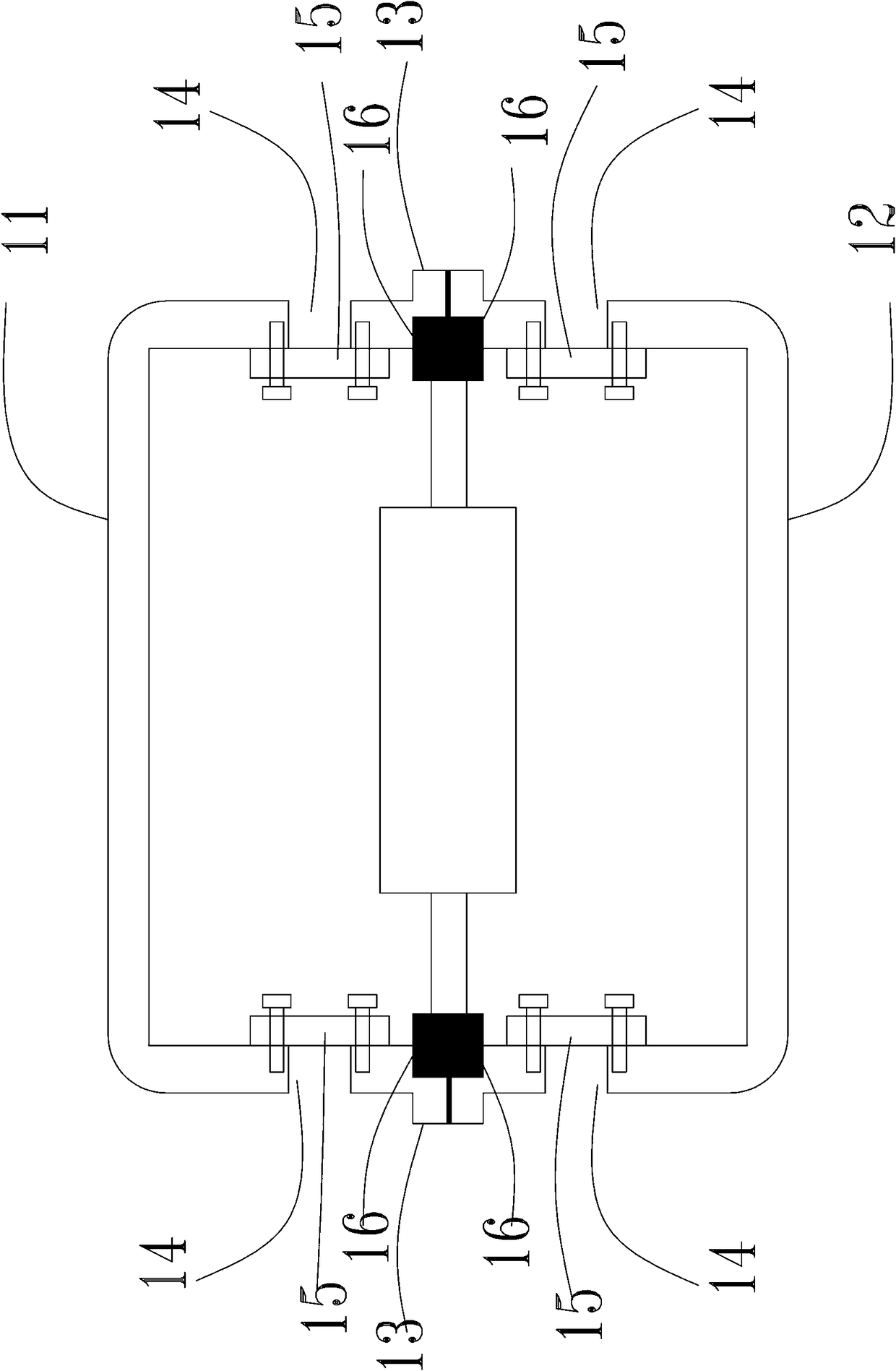
[0020] Such as Figure 1-3 As shown, it is a preferred embodiment of the present invention, a kind of optical cable splice closure 1, comprises the upper shell 11 and the lower shell 12 that are connected by connecting piece, the longitudinal side walls of the upper shell 11 and the lower shell 12 are respectively provided with opposite The upper semi-circular hole and the lower semi-circular hole, the upper semi-circular hole and the lower semi-circular hole form a circular optical cable connection hole 13, and the lateral side walls of the upper shell 11 and the lower shell 12 are respectively provided with sequentially arranged holes 14, the upper shell 11 and the lower shell The hole 14 corresponding to the inner side wall of 12 is fixedly pro...


PUM


Abstract

The invention discloses an optical cable splice box. The optical cable splice box comprises an upper casing and a lower casing which are connected through a connecting piece, wherein an upper semi-circular hole and a lower semi-circular hole which are opposite to each other are formed in the longitudinal side walls of the upper casing and lower casing respectively; a round optical cable connectinghole is formed by the upper semi-circular hole and the lower semi-circular hole; sequentially arranged holes are formed in the transverse side walls of the upper casing and lower casing respectively;ventilating pad layers are fixed at the holes corresponding to the inner side walls of the upper casing and the lower casing, and each ventilating pad layer comprises a shading layer, a waterproof and breathable layer and a metal mesh layer from outside to inside. According to the optical cable splice box, the phenomenon of uneven expansion or shrinkage due to different environmental temperaturedifference can be reduced, and the problem of loosening at the joint of the optical cable is solved.

Description

technical field [0001] The invention relates to the technical field of communication, in particular to an optical cable joint box. Background technique [0002] The optical cable splice box is a component that connects and protects two or more optical cables, and is one of the important equipment in the optical cable line. Widely used in communications, network systems, closed-circuit television monitoring systems, etc. Optical cable splice closures in existing finished products are generally made of plastic, such as ABS, and there are also optical cable splice closures made of materials such as polycarbonate. The outer layer of the optical cable is generally made of polypropylene material, and the joint is made of metal material. Due to the different thermal expansion coefficients of these optical cable components and the optical cable splice box, the thermal shrinkage performance of various materials is also different under different stresses or thermal environments, resu...

Claims


Application Information

Patent Timeline
IPC IPC(8): G02B6/44
Inventor 宗敏
Owner U COM TELECOM EQUIP CO LTD
Why Eureka
Try Eureka