A device and method for carbon coating modification of negative electrode material of lithium ion battery
A technology of lithium-ion batteries and negative electrode materials, applied in battery electrodes, secondary batteries, circuits, etc.
- Summary
- Abstract
- Description
- Claims
- Application Information
AI Technical Summary
Problems solved by technology
Method used
Image
Examples
Embodiment 1
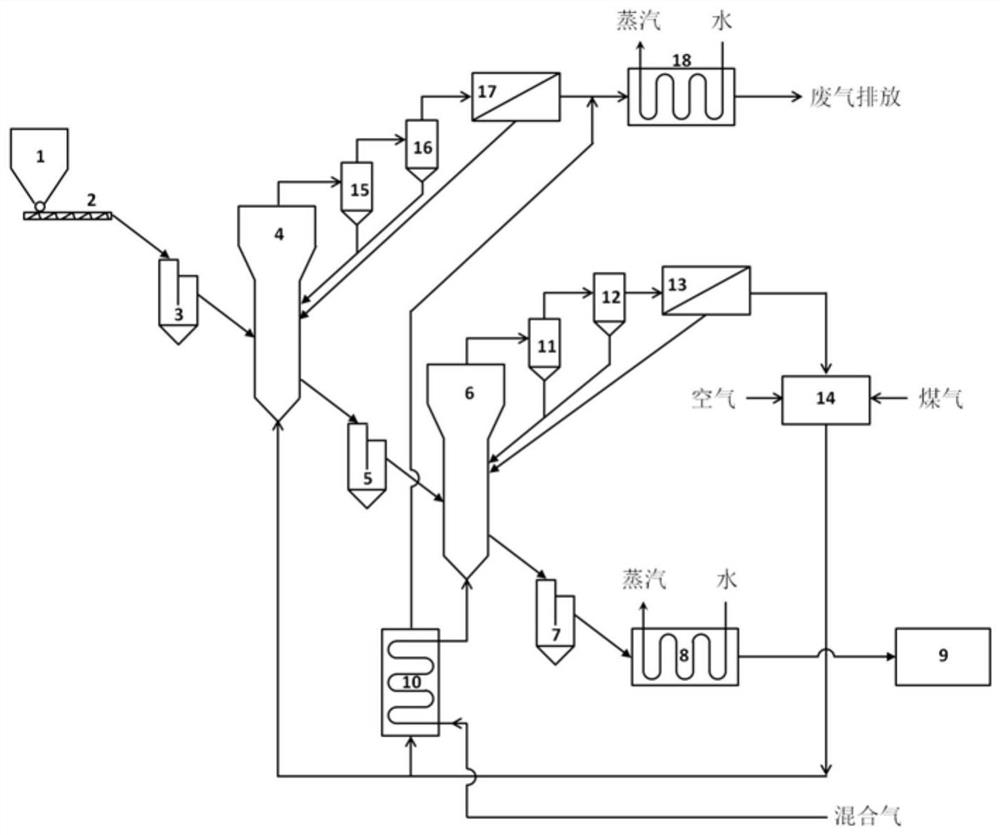
[0039] A system for carbon coating and modification of negative electrode materials for lithium-ion batteries
[0040] like figure 1 As shown, the device system includes sequentially connected silo 1, screw feeder 2, preheater feed valve 3, fluidized bed powder preheater 4, reactor feed valve 5, fluidized bed reaction 6, reactor discharge valve 7, product cooler 8, product collector 9, mixed gas preheater 10, primary reaction tail gas cyclone separator 11, secondary reaction tail gas cyclone separator 12, reaction tail gas bag dust collection Device 13, reaction exhaust gas burner 14, primary preheating exhaust gas cyclone separator 15, secondary preheating exhaust gas cyclone separator 16, preheating exhaust gas bag filter 17 and preheating exhaust gas cooler 18;
[0041] The discharge port of the silo 1 is connected with the feed port of the screw feeder 2, and the discharge port of the screw feeder 2 is connected with the feed port of the preheater feed valve 3, the The d...
Embodiment 2
[0044] A method for carbon coating modification of lithium ion battery negative electrode material
[0045] The method for carbon coating modification includes the following steps: the negative electrode material powder enters the fluidized bed powder preheater 4 from the silo 1 through the screw feeder 2 and the preheater feed valve 3 for a certain period of time, Return to the fluidized bed powder preheater 4 after being collected by the primary preheating tail gas cyclone separator 15, the secondary preheating tail gas cyclone separator 16 and the preheating tail gas bag filter 17; After the outlet of the heater 4 is discharged, it enters the fluidized bed reactor 6 through the reactor feed valve 5 and stays for a certain period of time, and passes through the primary reaction tail gas cyclone separator 11, the secondary reaction tail gas cyclone separator 12 and the reaction tail gas cloth bag After being collected by the dust collector 13, return to the fluidized bed reac...
Embodiment 3
[0048]Using the modification process described in Example 2, the silicon material is preheated in the fluidized bed powder preheater 4 from the silo 1 through the screw feeder 2 and the preheater feed valve 3, and the preheating temperature is The temperature is 900°C, and the preheating time is 10 minutes. The preheated material powder enters the fluidized bed reactor 6 through the reactor feed valve 5, and the mixed gas of methane / argon (the volume concentration of methane is 25%) passes through the mixed gas. In the preheater 10, the preheated mixed gas is uniformly fed into the bottom inlet of the fluidized bed reactor 6, so that the silicon powder in the fluidized bed reactor 6 is in a fluidized state. In the fluidized bed, the mixed gas is in full contact with the silicon powder, the operating temperature of the fluidized bed reactor 6 is controlled at 1200° C., and the residence time of the silicon powder in the fluidized bed is 10 minutes. The reacted silicon powder fl...
PUM
 Abstract
Description
Claims
Application Information
 - R&D
- Intellectual Property
- Life Sciences
- Materials
- Tech Scout
- Unparalleled Data Quality
- Higher Quality Content
- 60% Fewer Hallucinations
Browse by: Latest US Patents, China's latest patents, Technical Efficacy Thesaurus, Application Domain, Technology Topic, Popular Technical Reports.
© 2025 PatSnap. All rights reserved.Legal|Privacy policy|Modern Slavery Act Transparency Statement|Sitemap|About US| Contact US: help@patsnap.com


