Monitoring equipment for plant area

A technology for monitoring equipment and factory areas, which is applied in the direction of mechanical equipment, supporting machines, machine tables/supports, etc. It can solve problems such as inability to adjust angles, increase factory operating investment costs, and fail to meet the needs of large factories, so as to avoid sun exposure Rain, increase the effect of monitoring range

Inactive Publication Date: 2018-11-16
永康市翌阳科技有限公司
View PDF0 Cites 2 Cited by
  • Summary
  • Abstract
  • Description
  • Claims
  • Application Information

AI Technical Summary

Problems solved by technology

[0002] In large factories, monitoring probes will be installed in every corner to facilitate real-time monitoring of the situation in the factory, and can effectively monitor the situation of the personnel in the factory to prevent accidents. The existing monitoring probes are basically installed in the buildings of the factory. Most of the monitoring probes are fixed on the outer wall and monitor in one direction, so the angle cannot be adjusted, and it cannot meet all-round monitoring and detection. In addition, the existing monitoring probes are directly exposed to the sun and rain. Therefore, the service life of the monitoring probe will be greatly reduced, thereby increasing the operating cost of the factory, so the existing monitoring probe cannot meet the needs of large-scale factories.

Method used


Image

  • Monitoring equipment for plant area
  • Monitoring equipment for plant area
  • Monitoring equipment for plant area

Examples


Embodiment Construction

[0022] The preferred embodiments of the present invention will be described in detail below in conjunction with the accompanying drawings, so that the advantages and features of the present invention can be more easily understood by those skilled in the art, so as to define the protection scope of the present invention more clearly.

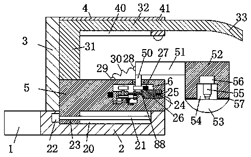
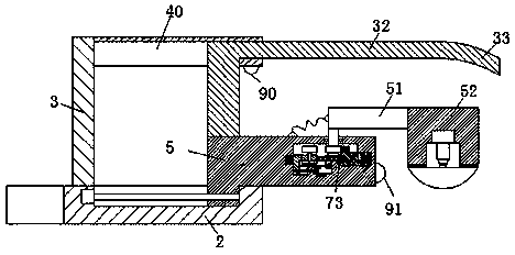
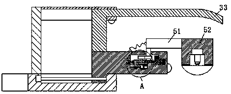
[0023] Such as Figure 1-4As shown, a monitoring device used in a factory area of ​​the present invention includes an installation block 1 for fixed installation on a building wall and a bracket 2 fixedly connected with the installation block 1, and the top left of the bracket 2 The side is fixedly provided with a support plate 3, and the top of the right side of the support plate 3 is fixedly provided with a first cover plate 4, and the bottom surface of the first cover plate 4 is provided with a first cover plate groove 40, and the first cover plate 4 The right end is provided with a second cover plate groove 41 communicating with the first cov...


PUM


Abstract

The invention discloses monitoring equipment for a plant area. The monitoring equipment comprises a mounting block fixedly mounted on a building wall body and a bracket fixedly connected to the mounting block. The monitoring equipment is characterized in that a supporting plate is fixedly arranged on the left side of the top of the bracket; a first cover plate is fixedly arranged on the top of theright side of the supporting plate; a first cover plate groove is formed in the bottom end surface of the first cover plate; and a second cover plate groove communicating to the first cover plate groove is formed in the right end of the first cover plate. The monitoring equipment disclosed by the invention is simple in structure and safe and reasonable in design. The position of a monitoring probe in left and right directions and the rotating angel position of the monitoring probe can be adjusted automatically, and the height of the monitoring probe can be also adjusted, so that the plant area can be monitored all around by the monitoring probe. The first cover plate and the second cover plate can better prevent rain, shield sun and prevent dust. The service life of the monitoring probe is prolonged, the input cost of a plant is reduced, and the whole monitoring equipment is safe and stable to operate, simple, convenient and rapid to operate and suitable for a large plant area.

Description

technical field [0001] The invention belongs to the technical field of monitoring, and in particular relates to a monitoring device used in a factory area. Background technique [0002] In large factories, monitoring probes will be installed in every corner to facilitate real-time monitoring of the situation in the factory, and can effectively monitor the situation of the personnel in the factory to prevent accidents. The existing monitoring probes are basically installed in the buildings of the factory. Most of the monitoring probes are fixed on the outer wall and monitor in one direction, so the angle cannot be adjusted, and it cannot meet all-round monitoring and detection. In addition, the existing monitoring probes are directly exposed to the sun and rain. Therefore, the service life of the monitoring probe will be greatly reduced, thereby increasing the operating cost of the factory. Therefore, the existing monitoring probe cannot meet the use requirements in large fac...

Claims


Application Information

Patent Timeline
Patent Type & Authority Applications(China)
IPC IPC(8): F16M11/04F16M11/06
CPCF16M11/045F16M11/046F16M11/06
Inventor 梁梦迪
Owner 永康市翌阳科技有限公司
Why Eureka
Try Eureka