Empennage stable high-speed supercavitation projectile
A technology of supercavitation and fins, which is applied in the direction of projectiles, offensive equipment, weapon types, etc., can solve the problems of high resistance of underwater projectiles, poor trajectory stability, and fast velocity attenuation, etc., to achieve increased range and reduced viscous resistance , the effect of reducing fluid resistance
- Summary
- Abstract
- Description
- Claims
- Application Information
AI Technical Summary
Problems solved by technology
Method used
Image
Examples
Embodiment 1
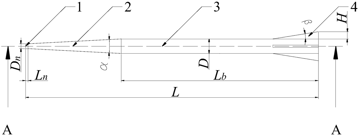
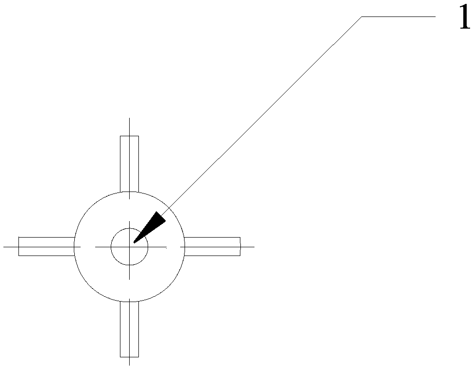
[0035] refer to Figure 1-Figure 4 , The empennage-stabilized high-speed supercavitation projectile in this embodiment consists of four parts, namely a flat-head disc cavitator 1, a shoulder truncated cone transition section 2, a rear cylinder 3, and a tail triangular empennage 4. The head cavitator in this embodiment adopts a flat-head disc cavitator, and its flat head and sharp edges induce cavitation when moving at high speed, and in order to make the maximum cross-sectional area of the generated cavitation not smaller than the cross-sectional area of the projectile , it should be ensured that the value of the flat head disc cavitator 1 is within a certain reasonable range, and its diameter D is usually selected n It is 1 / 4~1 / 3 of the diameter D of the rear cylinder 3, in this embodiment D n Take 4mm, the length L of the head cavitator n Take 2mm, the taper angle α of the shoulder truncated cone transition section 2 is taken as 6°, the diameter D of the rear cylinder ...
Embodiment 2
[0037] refer to Figure 5 and Figure 6 The difference between this embodiment and Embodiment 1 is that a plurality of annular grooves are provided in the middle of the projectile body, specifically, the surface of the rear cylinder 3 is provided with such as figure 2 The multiple annular grooves shown in , the projectile body bears the force of the projectile rest on the projectile body through the grooves when launching, disperses and bears the huge impact force during launch, and reduces the excessive instantaneous impact on the bottom of the projectile during launch and causes Structural damage.
Embodiment 3
[0039] The difference between this embodiment and Embodiment 1 and Embodiment 2 is that the head flat disk-shaped cavitator 1 of the projectile adopts Figure 7 , Figure 8 In order to facilitate the stability of entering the water and the stability of the ballistic trajectory of the underwater movement, the cone head cavitator in the model usually adopts a cone head cavitator with a larger cone angle, which can be 120°, 135°, etc. The supercavitation generated by the carburetor can completely wrap the projectile, and the bottom surface diameter D of the head cone cavitator should be guaranteed n Not less than 1 / 4 of the diameter D of the rear cylinder 3, generally 1 / 4 to 1 / 3.
[0040] The head cavitator adopts a flat-head disc-shaped cavitator or a cone-shaped cavitator. The cavitator has a clear outline. When the projectile moves at high speed in water, the edge of the cavitator starts to cavitate first, and further increases with the speed. Induce supercavitation that com...
PUM
 Abstract
Description
Claims
Application Information
 - R&D
- Intellectual Property
- Life Sciences
- Materials
- Tech Scout
- Unparalleled Data Quality
- Higher Quality Content
- 60% Fewer Hallucinations
Browse by: Latest US Patents, China's latest patents, Technical Efficacy Thesaurus, Application Domain, Technology Topic, Popular Technical Reports.
© 2025 PatSnap. All rights reserved.Legal|Privacy policy|Modern Slavery Act Transparency Statement|Sitemap|About US| Contact US: help@patsnap.com


