Fall detection system and method
A detection device and axis technology, applied in the field of security detection, can solve the problems of high equipment cost, low detection accuracy, inconvenient use of fall detection equipment, etc., and achieve the effect of avoiding complicated steps and ensuring safety.
- Summary
- Abstract
- Description
- Claims
- Application Information
AI Technical Summary
Problems solved by technology
Method used
Image

Examples
Embodiment 1
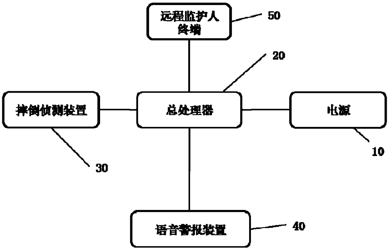
[0019] Example 1: Please refer to the attached figure 1 , a fall detection system, including a power supply 10, a general processor 20, a fall detection device 30, a voice alarm device 40, and a remote guardian terminal 50, wherein the general processor 20 is connected to the power supply 10, the The fall detection device 30, the voice alarm device 40, and the remote guardian terminal 50 are connected.
[0020] The connection is an electrical connection, and the power supply 10 is an independent power supply, which can ensure the entire independent power supply of the detection system.
Embodiment 2
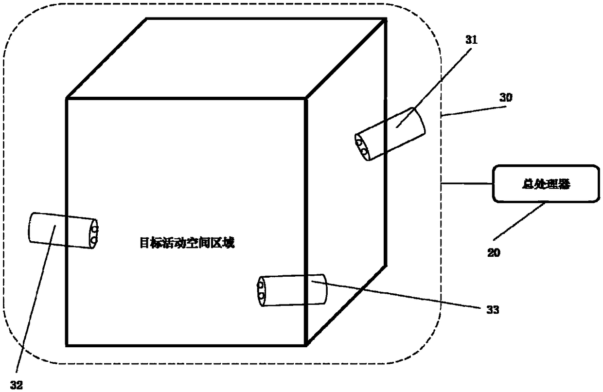
[0021] Embodiment 2: Please refer to the attached figure 1 - attached figure 2 , a fall detection system, the basic structure is the same as that of Embodiment 1, the difference is that the fall detection device 30 includes a first axis capture camera 31, a second axis capture camera 32, a third axis capture camera 33. The first axis capture camera 31, the second axis capture camera 32, and the third axis capture camera 33 are respectively located at the upper, middle, and lower parts of the corners of the target activity space area, and are used to capture image data of different positions of the human body and Relevant data is sent to general processor 20, and described camera all adopts 3D camera, and described general processor 20 is connected with described fall detection device 30 as first axis capture camera 31, second axis capture camera 32, The third axis capture camera 33 is connected with the general processor 20 .
[0022] The general processor 20 receives the i...
Embodiment 3
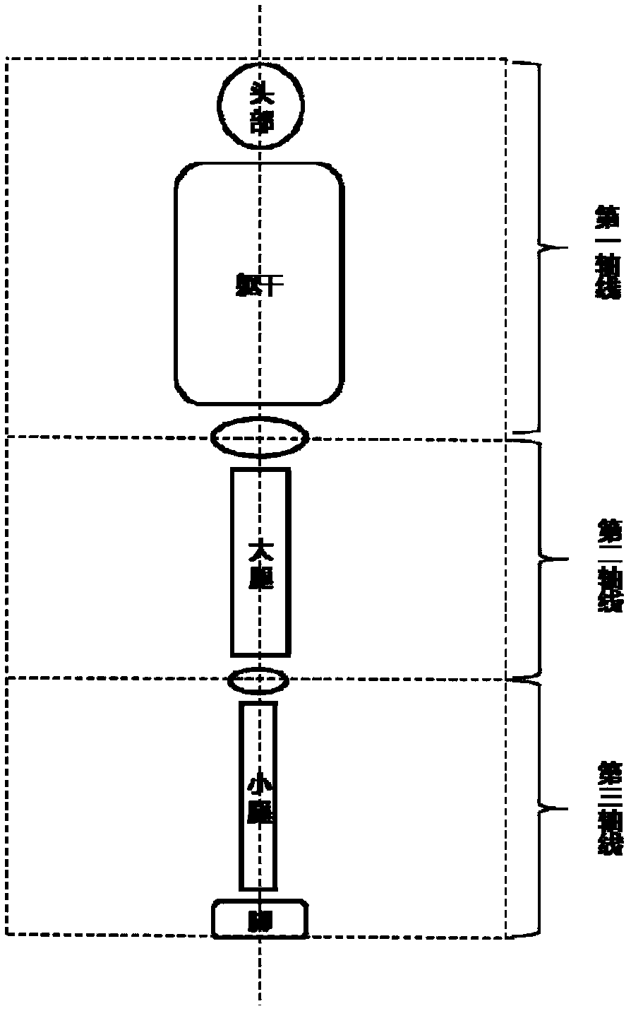
[0023] Embodiment 3: Please refer to the attached figure 1 - attached image 3 . A fall detection method comprising,
[0024] (1) Image acquisition step, capture the image data within the scope of the target activity space area by the first axis capture camera 31, the second axis capture camera 32, and the third axis capture camera 33 of the fall detection device 30, and store the image data transmitted to the general processor 20;
[0025] (2) In the mirror detection step, the general processor 20 performs background difference calculation on the image data acquired by the first axis capture camera 31, the second axis capture camera 32, and the third axis capture camera 33 respectively, after calculation, when the first When the image data of the axis capture camera, the second axis capture camera, and the third axis capture camera simultaneously detect that someone enters the range of the target activity space area, fall detection is started;
[0026] (3) Fall detection ...
PUM
 Abstract
Description
Claims
Application Information
 - R&D Engineer
- R&D Manager
- IP Professional
- Industry Leading Data Capabilities
- Powerful AI technology
- Patent DNA Extraction
Browse by: Latest US Patents, China's latest patents, Technical Efficacy Thesaurus, Application Domain, Technology Topic.
© 2024 PatSnap. All rights reserved.Legal|Privacy policy|Modern Slavery Act Transparency Statement|Sitemap