Transmission mechanism and washing machine

A technology of a transmission mechanism and a washing machine, which is applied in the field of washing machines, can solve the problems of poor stability of the delivery box and large occupied space and volume.

Pending Publication Date: 2018-11-23
NANJING ZHONGJINGKE ELECTRONICS TECH
View PDF4 Cites 0 Cited by
  • Summary
  • Abstract
  • Description
  • Claims
  • Application Information

AI Technical Summary

Problems solved by technology

[0005] The purpose of the present invention is to provide a transmission mechanism and a washing machine, which solves the problem that the structure of the spring assembly and the rotary damper in the prior art is separately arranged, and occupies a large space, and at the same time solves the problem that the push-in and ejection process of the delivery box is stable sex problem

Method used


Image

  • Transmission mechanism and washing machine
  • Transmission mechanism and washing machine
  • Transmission mechanism and washing machine

Examples


Embodiment 1

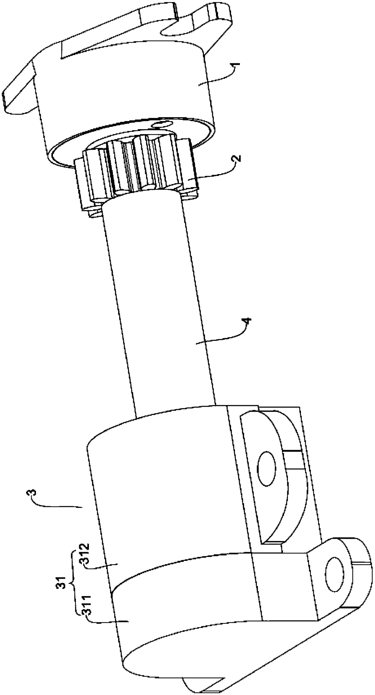
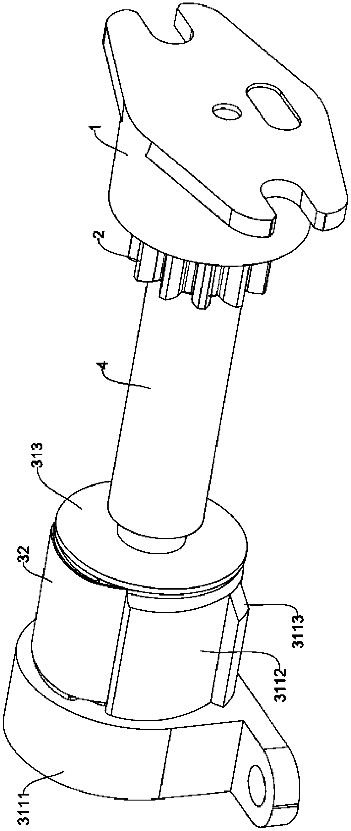
[0044] like Figure 1-4 As shown, a transmission mechanism is provided in this embodiment, including a rotary damper 1, a rotating wheel 2, a transmission rod 4 and a spring assembly 3, wherein the transmission rod 4 is a cylindrical stepped shaft, and the transmission rod in this embodiment 4 is integrally formed with the output shaft of the rotary damper 1, and an integrally formed rotating shaft (the following rotating shaft is the same as the rotating shaft here) is used to replace the output shaft and transmission rod 4 in the existing rotary damper 1 . In addition, the transmission rod 4 and the output shaft of the rotary damper 1 can be arranged separately, and the transmission rod 4 and the output shaft are installed coaxially during assembly.

[0045] The rotary damper 1 is fixed on the washing machine, and the rotating wheel 2 is arranged on the rotating shaft, and its specific position is adjusted according to the position of the transmission structure engaged with ...

Embodiment 2

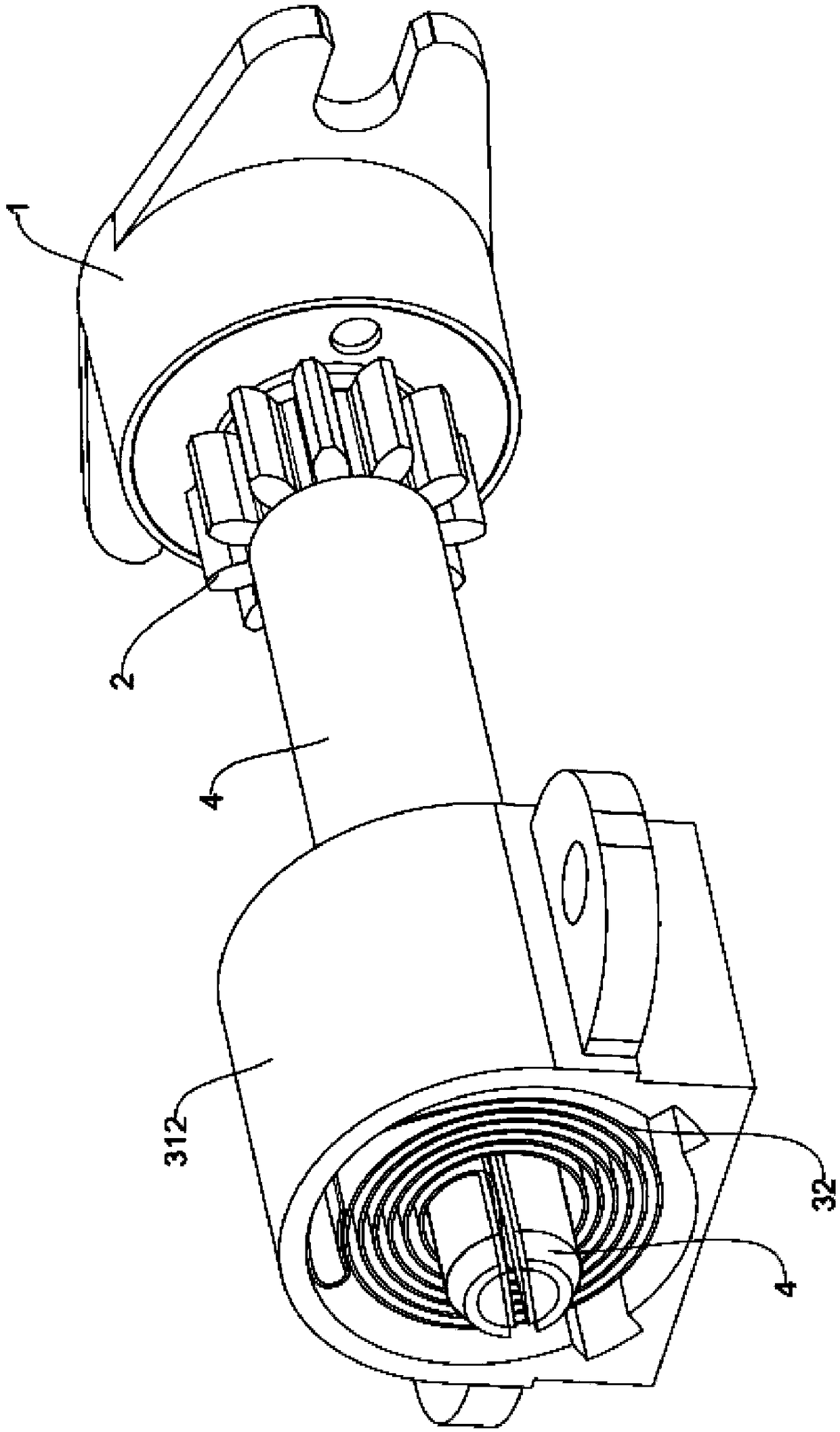
[0055] This embodiment also provides a transmission mechanism, the elastic component is arranged on the outer periphery of the damper, and the spring component 3 can make the drop box pop out.

[0056] The spring assembly 3 includes a second clockwork spring (not shown in the figure) and a second spring holder (not shown in the figure), wherein the second spring holder is fixed on the washing machine, and the second clockwork spring is arranged on the second clockwork spring. In the second spring fixing seat, two ends of the second clockwork spring are respectively connected to the shell of the rotary damper 1 and the washing machine, and the rotary damper 1 is located inside the second clockwork spring. At this time, it is no longer necessary to set the transmission rod, the rotating wheel 2 is fixedly installed on the shell of the rotary damper 1, the output shaft of the rotary damper 1 is fixed and does not rotate, and the rotating wheel 2 and the shell of the rotary damper ...


PUM


Abstract

The invention relates to the technical field of washing machines and discloses a transmission mechanism and a washing machine. The transmission mechanism comprises a rotary damper, a rotating wheel and a spring assembly, wherein the rotating wheel is arranged on an output shaft of the rotary damper; the rotating wheel is in transmission connection with a feeding box of the washing machine; the spring assembly is arranged on the output shaft of the rotary damper or is arranged at the periphery of the rotary damper; when the feeding box is pushed into the washing machine, the feeding box drivesthe rotating wheel to rotate; the spring assembly is used for accumulating energy; when the feeding box is pressed again, the spring assembly can drive the rotating wheel to eject out the feeding box.By adopting the transmission mechanism and the washing machine, the problems in the prior art that structures of the spring assembly and the rotary damper are arranged separately and the volume of the occupied space is large are solved; meanwhile, the problem that the stability of a pushing-in and ejecting-out process of the feeding box is poor is also solved.

Description

technical field [0001] The invention relates to the technical field of washing machines, in particular to a transmission mechanism and a washing machine. Background technique [0002] When people wash clothes, they need to put detergent into the detergent box of the washing machine. When the box is pulled out or pushed into the shell of the washing machine, a damping mechanism is usually provided to ensure that the detergent box can be pulled out or pushed smoothly. enter. [0003] The buffer structure of the delivery mechanism in the prior art to the delivery box includes a rotary damper and a spring assembly. The spring assembly is a commonly used extension spring. The installation position of the rotary damper is determined according to the stroke that the delivery box can be pulled out of the washing machine shell, for example, When the dropping box is pulled out of the shell to be half of the length of the dropping box, the rotary damper is installed in the middle of t...

Claims


Application Information

Patent Timeline
Patent Type & Authority Applications(China)
IPC IPC(8): D06F37/40D06F39/02
CPCD06F37/40D06F39/02
Inventor 李玉娇应文董晶晶
Owner NANJING ZHONGJINGKE ELECTRONICS TECH
Why Eureka
Try Eureka