A flexion and extension device based on directional wheel meshing transmission and its application method

A technology of directional wheels and driving devices, which is applied in the direction of transmission devices, friction transmission devices, belts/chains/gears, etc., can solve problems such as low expansion and contraction efficiency, high hydraulic transmission costs, poor force resistance of synchronous belts, etc., and achieve enhanced flexion and extension strength , to achieve the effect of telescopic operation and low manufacturing cost

Active Publication Date: 2022-01-11
YUEXI COUNTY GREAT WALL MACHINERY
View PDF8 Cites 0 Cited by
  • Summary
  • Abstract
  • Description
  • Claims
  • Application Information

AI Technical Summary

Problems solved by technology

First of all, the expansion and contraction is realized through the alignment of the timing belt. The biggest problem is that the force of the timing belt is poor, and the connection points of each timing belt are not strong enough, which will easily cause the output of the telescopic device to break and bend suddenly at a long distance. ; Secondly, the cost of hydraulic transmission is relatively high, and the supporting construction of the transmission is large, which is not economical for engineering construction; finally, the progressive construction method through scaffolding is the traditional telescopic method, which has low telescopic efficiency and high labor construction costs.

Method used


Image

  • A flexion and extension device based on directional wheel meshing transmission and its application method
  • A flexion and extension device based on directional wheel meshing transmission and its application method
  • A flexion and extension device based on directional wheel meshing transmission and its application method

Examples


Embodiment Construction

[0029] In order to make the purpose, technical solutions and advantages of the embodiments of the present invention clearer, the technical solutions of the present invention will be clearly and completely described below in conjunction with the accompanying drawings. Obviously, the described embodiments are part of the embodiments of the present invention, not all of them. the embodiment. Based on the embodiments of the present invention, all other embodiments obtained by persons of ordinary skill in the art without making creative efforts belong to the protection scope of the present invention.

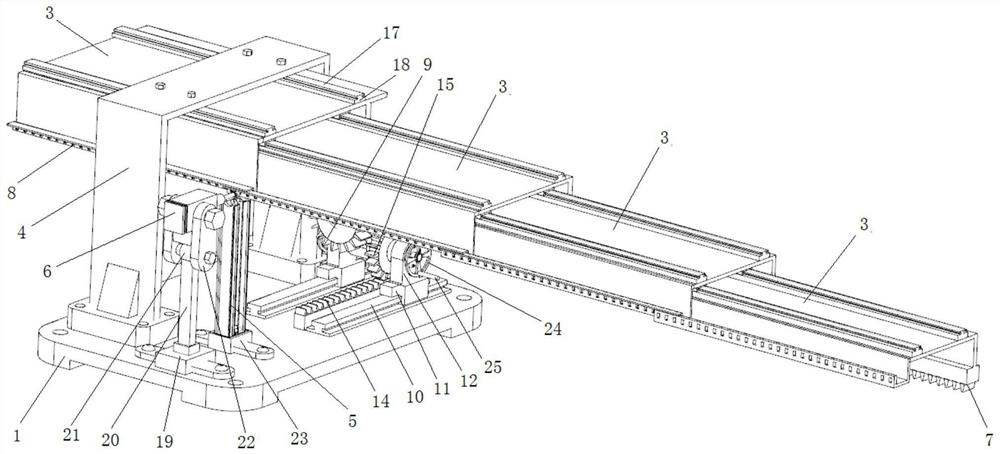
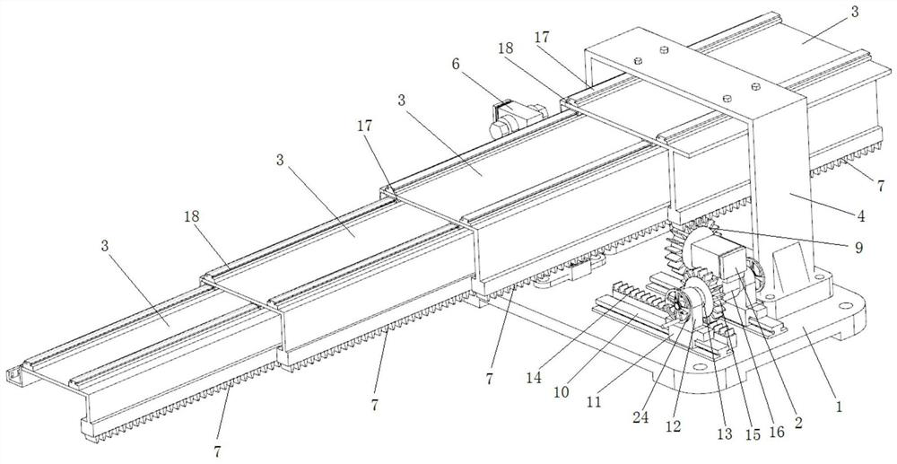
[0030] As a specific embodiment of the present invention, in combination with figure 1 and figure 2As shown, a flexion and extension device based on the meshing transmission of directional wheels includes a base 1, a driving device 2, a gantry bracket 4, a fastener receiving box 5, a screwing device 6 and n flexion and extension bodies 3, where n is not less than 2 is a positive i...


PUM


Abstract

The invention discloses a flexion and extension device based on directional wheel bar meshing transmission and a use method. The gantry bracket is fixed on the base, and the bottom of each flexion and extension body is provided with grooves extending to both ends of itself. The bottom of each flexion and extension body is along the The first rack is fixed in the extending direction of the groove, and several positioning holes are opened on the other side wall of each flexing and extending body along the extending direction of the groove; the first flexing and extending body is slidably connected to the gantry bracket, and the first flexing and extending body The sliding connection is in the groove of the first flexor-extension body, and so on, the n-th flexor-extension body is slidingly connected in the groove of the n-1 flexor-extension body; The first gear, the first gear can be meshed with the first rack on any flexion and extension body; the fastener receiving box and the screwing device are fixed on the base, and the screwing device is located on the side where the positioning hole is opened on the flexion and extension body, The fastener accommodating box is located between the screwing device and the flexion and extension body, and the flexion and extension transmission effect of the present invention is better.

Description

technical field [0001] The invention belongs to the field of structural design of a transmission system of a flexion and extension device, and in particular relates to a flexion and extension device and a use method based on meshing transmission of directional wheel bars. Background technique [0002] In the field of conventional construction machinery, long-distance flexion and extension devices have broad application prospects. A good and efficient transmission of flexion and extension devices will effectively ensure the stability and effectiveness of the output body. In the existing transmission mechanism, the mechanical structure system that can flex and extend for a long distance Relatively small. [0003] Among the existing telescopic devices, some schemes realize the expansion and contraction by aligning the synchronous belt, some realize the expansion and contraction through the hydraulic transmission, and some realize the contraction through the progressive construc...

Claims


Application Information

Patent Timeline
Patent Type & Authority Patents(China)
IPC IPC(8): F16H19/04
CPCF16H19/04
Inventor 赵向杰房拴娃
Owner YUEXI COUNTY GREAT WALL MACHINERY
Why Eureka
Try Eureka