
Multifunctional spectacle

A multi-functional glasses technology, applied in the field of glasses, can solve problems such as inability to wear, small bolt size, loose bolts and falling off, etc., to save the time to find bolts, improve work efficiency, and reduce the effect of connecting parts

Inactive Publication Date: 2018-11-23
临海市大宇眼镜有限公司
View PDF0 Cites 4 Cited by
  • Summary
  • Abstract
  • Description
  • Claims
  • Application Information

AI Technical Summary

Problems solved by technology

[0003] Existing glasses are limited by the length of the temples. When purchasing glasses, it is very difficult to choose an ideal pair of lenses. Moreover, when the user performs slight or even vigorous exercise, the temples are easily detached due to vibration. Ears cause the glasses to slip off, causing inconvenience to the user; and the bolts used to connect the frame and temples of the existing glasses are small in size. If there is no special device for placing the bolts during disassembly, the bolts will often be lost, and the bolts will be lost during use. After a period of time, it will be difficult to find the bolts that loosen and fall off, so that they cannot be installed back in time, resulting in inability to wear and causing inconvenience to life, so it is necessary to improve

Method used


Image

  • Multifunctional spectacle
  • Multifunctional spectacle
  • Multifunctional spectacle

Examples


Embodiment Construction

[0022] The following descriptions are only preferred embodiments of the present invention, and do not limit the protection scope of the present invention. The present invention will be further described below in conjunction with the accompanying drawings and embodiments.

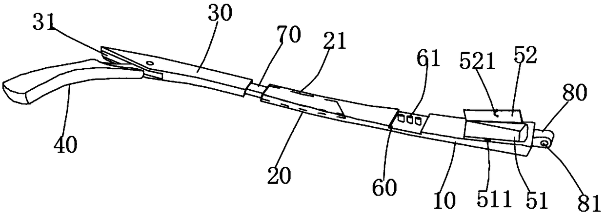
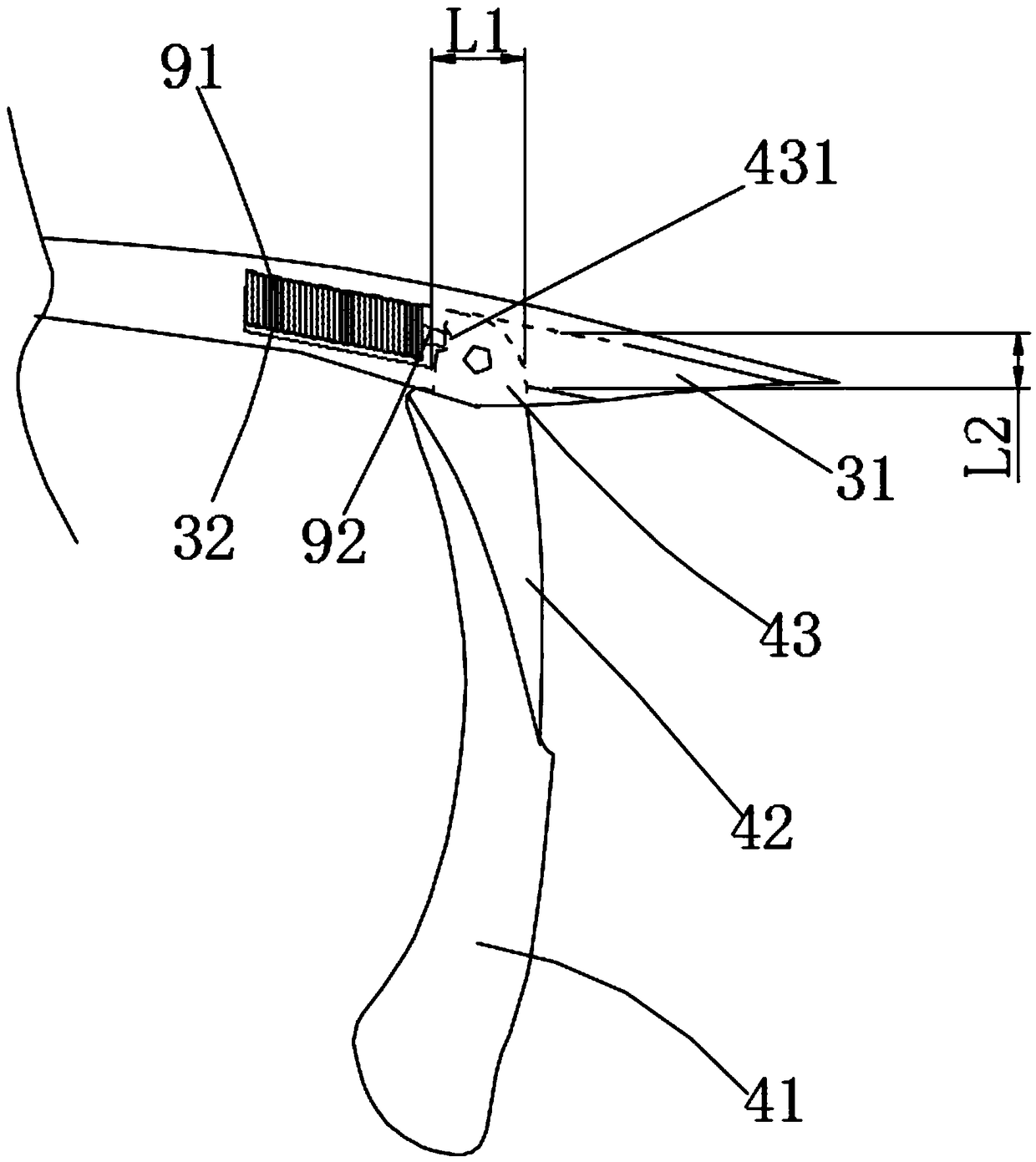
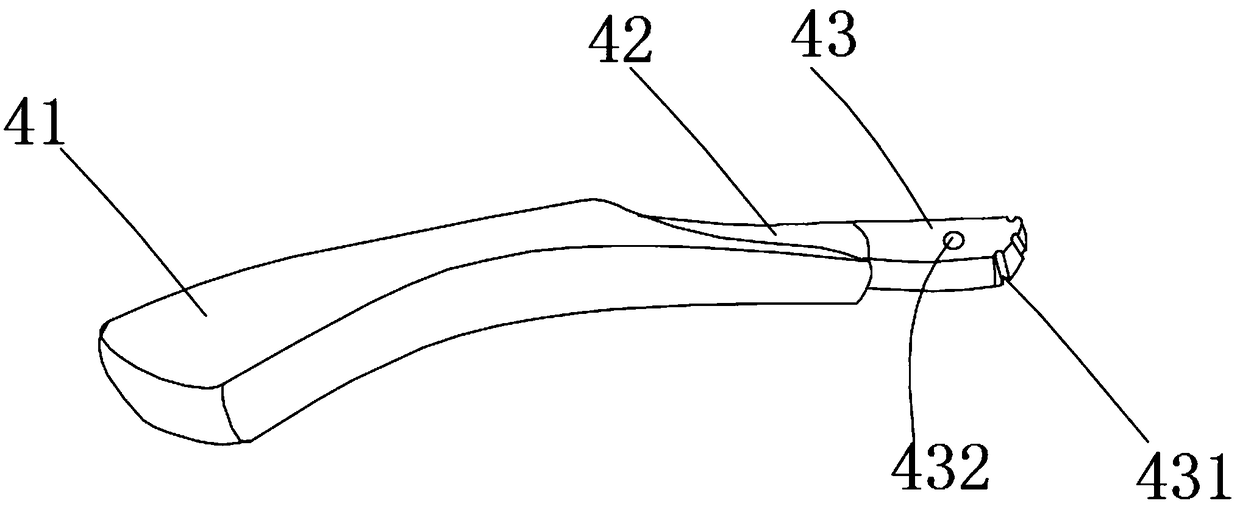
[0023] Examples, see Figure 1 to Figure 5 Shown: a multifunctional mirror frame, including a mirror frame and mirror legs, characterized in that: it also includes a rotating shaft (not marked in the figure), wherein the mirror legs include a first body 10, a second body 20, a third body 30 and bend 40,

[0024] Wherein the third body 30 and the bending part 40 are rotatably connected by a rotating shaft, and the third body 30 is provided with a third accommodation chamber 32 and a third groove 31 with oblique openings, and a spring 91 is arranged in the third accommodation chamber 32 , the spring 91 is connected with an arc-shaped protrusion 92, and the specific spring 91 and the arc-shaped protrusion 92 c...


PUM


Abstract

The invention discloses a multifunctional spectacle frame which comprises a spectacle frame, spectacle legs and rotary shafts. Each spectacle leg comprises a first body, a second body, a third body and a bending part; each third body is rotatably connected with the bending part through the corresponding rotary shaft; a third holding cavity and a third groove with an inclined opening are arranged on each third body; each bending part comprises a rotary part located in each third groove, a connecting part, and a third main body matched with each third groove; a spring is arranged in each third holding cavity; an arc-shaped clamping bulge is connected onto each spring; a positioning groove matched with each arc-shaped clamping bulge is arranged on each rotary part; a second holding cavity isarranged in each second body; a small telescopic rod is arranged on each third body; each second body sleeves on the outer part of each small telescopic rod; each small telescopic rod stretches out and draws back through a bolt; each bolt is located on the side edge of a small second body. The multifunctional spectacle frame has the characteristics that the length of each spectacle leg and the angle of each bending part can be adjusted so as to adapt to a wearer in a human friendly manner, and the first holding tank for placing bolts is arranged, so that the efficiency is improved.

Description

technical field [0001] The invention belongs to the technical field of spectacles, in particular to multifunctional spectacles. Background technique [0002] Glasses are a simple optical device made to correct vision or protect eyes. They are wearing tools and decorations that are often used in daily life. The glasses include mirror legs, and the mirror legs include connecting rod parts and hanging ear parts. When wearing the glasses, the hanging ear parts at the ends of the two mirror legs are hooked and placed on the ears of a human body. [0003] Existing glasses are limited by the length of the temples. When purchasing glasses, it is very difficult to choose an ideal pair of lenses. Moreover, when the user performs slight or even vigorous exercise, the temples are easily detached due to vibration. Ears cause the glasses to slip off, causing inconvenience to the user; and the bolts used to connect the frame and temples of the existing glasses are small in size. If there ...

Claims


Application Information

Patent Timeline
Patent Type & Authority Applications(China)
IPC IPC(8): G02C5/20G02C5/14G02C5/00
CPCG02C5/20G02C5/008G02C5/14
Inventor 项修强
Owner 临海市大宇眼镜有限公司
Learn More