Manufacturing device for electronic product

A technology of electronic products and equipment, which is applied in the field of electronic product manufacturing equipment, can solve the problems that affect the quality and speed of the preparation of flexible circuit boards, affect the production and processing efficiency of flexible circuit boards, and make it difficult to adjust the rotation direction of drill bits, etc., and achieve simple drilling steps Convenience, the adjustment steps are simple and convenient, and the effect of reducing manual operation steps

Inactive Publication Date: 2018-11-30
FOSHAN DETAO POWER TECH CO LTD
View PDF0 Cites 0 Cited by
  • Summary
  • Abstract
  • Description
  • Claims
  • Application Information

AI Technical Summary

Problems solved by technology

[0002] During the production and processing of flexible circuit boards, the punching of flexible circuit boards in the prior art mainly relies on manual adjustment and replacement of drill bits, and the use efficiency is low. When the drill bits need to be replaced repeatedly, repeated disassembly and assembly are required, which greatly affects the quality of flexible circuit board preparation and The preparation speed, and the traditional drilling equipment is not convenient to adjust the rotation direction of the drill bit. Therefore, the drilling limitation is strong, the use is inconvenient, and the production and processing efficiency of the flexible circuit board is affected, which needs to be improved.

Method used


Image

  • Manufacturing device for electronic product
  • Manufacturing device for electronic product
  • Manufacturing device for electronic product

Examples


Embodiment Construction

[0014] Combine below Figure 1-3 The present invention will be described in detail.

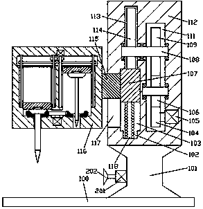
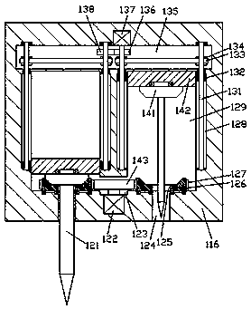
[0015] refer to Figure 1-3 According to an embodiment of the present invention, an electronic product production equipment includes a base frame 100, a support column 101 is fixed on the top end surface of the base frame 100, and an attachment frame 112 is fixed on the top end surface of the support column 101, so The left end of the attachment frame 112 is provided with a main base body 116, and the bottom end surface of the main base body 116 is provided with a first through groove 124 symmetrically left and right, and the inner top wall of the first through groove 124 is provided with a mobilization mechanism extending up and down. Groove 129, the bottom wall of the mobilization groove 129 is rotated and installed with a conical side frame 126, and the outer periphery of the conical side frame 126 is fixedly provided with a toothed ring 127, and the upper and lower sides of the conical s...


PUM


Abstract

The invention discloses a manufacturing device for an electronic product. The manufacturing device comprises a base frame, wherein a support pillar is fixedly arranged on the top end surface of the base frame; a mounting and clamping frame is fixedly arranged on the top end surface of the support pillar; a main seat body is arranged at the left side end of the mounting and clamping frame; first through grooves are formed in the bottom end surface of the main seat body in bilateral symmetry; an adjusting groove extending up and down is formed in the inner top wall of each first through groove;a cone edge frame is mounted at the bottom wall of each adjusting groove in a running fit manner; a toothing ring is fixedly arranged at the periphery of each cone edge frame; a second through grooveopposite to the corresponding first through groove is formed in each cone edge frame in an up-and-down penetrating manner; an adjusting frame is mounted in each adjusting groove in a sliding fit manner; a cone edge wheel for meshing with the cone edge frame is mounted at the bottom end of each adjusting frame in a running fit manner; a drill is fixedly mounted on the bottom end surface of each cone edge wheel; the drills correspondingly penetrate the second through grooves and the first through grooves; and a through opening is formed between the bottom ends of the adjusting grooves on the left side and the right side in a communicating manner.

Description

technical field [0001] The invention relates to the technical field of circuit board processing, in particular to electronic product manufacturing equipment. Background technique [0002] During the production and processing of flexible circuit boards, the punching of flexible circuit boards in the prior art mainly relies on manual adjustment and replacement of drill bits, and the use efficiency is low. When the drill bits need to be replaced repeatedly, repeated disassembly and assembly are required, which greatly affects the quality of flexible circuit board preparation and The preparation speed, and the traditional drilling equipment is not convenient to adjust the rotation direction of the drill bit. Therefore, the drilling limitation is strong, the use is inconvenient, and the production and processing efficiency of the flexible circuit board is affected, which needs to be improved. Contents of the invention [0003] The object of the present invention is to provide a...

Claims


Application Information

Patent Timeline
Patent Type & Authority Applications(China)
IPC IPC(8): B26F1/16B26D7/26B26D5/08B26D5/16
CPCB26F1/16B26D5/086B26D5/16B26D7/2628B26F2210/08
Inventor 陈柯
Owner FOSHAN DETAO POWER TECH CO LTD
Why Eureka
Try Eureka