A Fluid Reversing System Based on Hydraulic Pulse Control

A reversing system and hydraulic pulse technology, applied in the hydraulic field, can solve problems such as troublesome operation, mechanical failure, unsuitable electric switch, etc., and achieve the effects of convenient operation, wide application range and novel control method.

Active Publication Date: 2020-05-08
韶关一本机械设备有限公司
View PDF9 Cites 0 Cited by
  • Summary
  • Abstract
  • Description
  • Claims
  • Application Information

AI Technical Summary

Problems solved by technology

[0002] In the process of liquid transportation, when it is necessary to change the flow direction of the liquid, manual or electric switches are usually used to switch. These methods are very common, but there are some shortcomings. If these reversing switches are all manual switches, it will be extremely troublesome to operate, and if electric switches are used, the cost will increase, and the electric switches depend on the power supply, which is prone to various unpredictable accidents.
[0003] In addition, electric switches are not suitable for all occasions. For example, in farmland equipped with two switchable irrigation nozzles, it is not suitable to use electric switches, because water will affect the use and life of electric switches.
[0004] However, the manual switch needs to be operated manually, so there is a risk of injury and other operational accidents during operation. For example, in a large hydraulic oil circuit system, mechanical failures are prone to occur during the oil circuit switching process, which brings the risk of injury to workers, and the operation If the switch is not complete at the time, it is prone to switch rebound or internal conflict of the machine, which will cause unnecessary damage to the machine and processing line.

Method used


Image

  • A Fluid Reversing System Based on Hydraulic Pulse Control
  • A Fluid Reversing System Based on Hydraulic Pulse Control
  • A Fluid Reversing System Based on Hydraulic Pulse Control

Examples


Embodiment Construction

[0048] In order to make the technical means, creative features, goals and effects achieved by the present invention easy to understand, the present invention will be further described below in conjunction with specific embodiments.

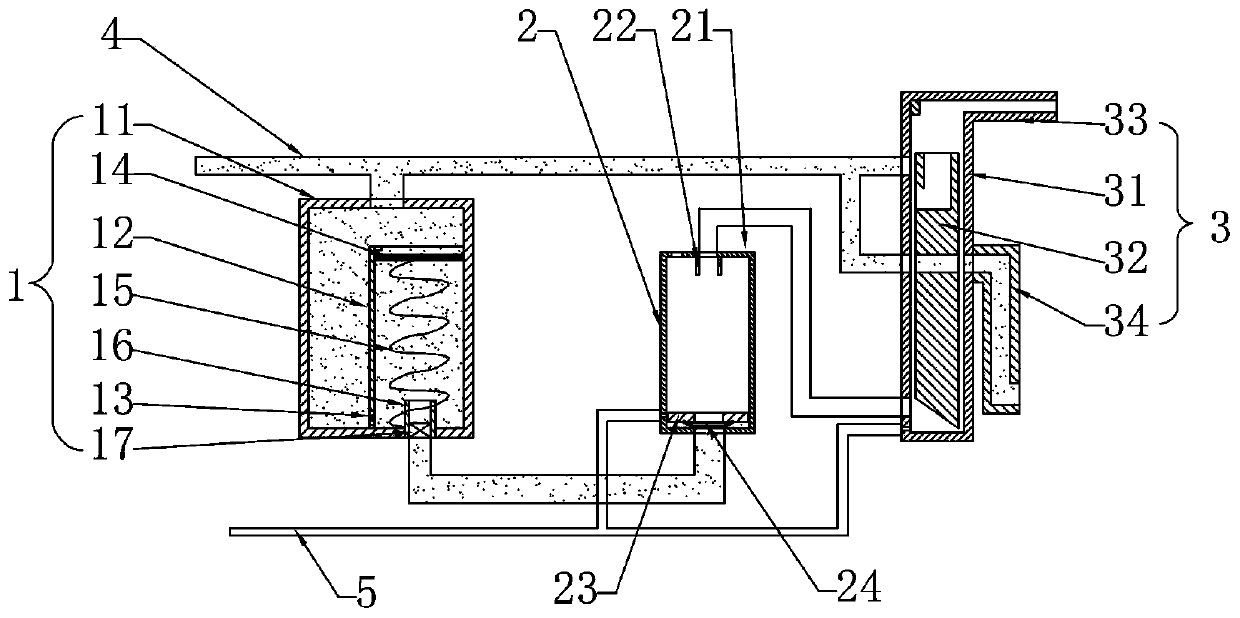
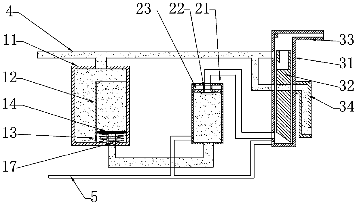
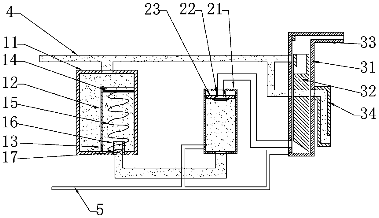
[0049] Such as figure 1 As shown, a fluid reversing system based on hydraulic pulse control in this embodiment includes a drive chamber 1 , a transfer chamber 2 , a reversing assembly 3 , an input pipe 4 and a return pipe 5 .

[0050]Such as figure 1 , Figure 5 As shown, the driving chamber 1 includes a main tank body 11 , an auxiliary tank body 12 , an inner one-way valve 13 , a push plate 14 , a return spring 15 , a receiving cylinder 16 and an outer one-way valve 17 .

[0051] The main tank body 11 is a cylindrical shell, and the top surface and the bottom surface of the main tank body 11 respectively have a through hole.

[0052] The auxiliary tank body 12 is a cylindrical thin-walled member, the auxiliary tank body 12 is located in the ma...


PUM


Abstract

The invention relates to the field of hydraulics, in particular to a fluid reversing system based on hydraulic impulse control. The fluid reversing system comprises a driving chamber, a transfer chamber, a reversing assembly, an input pipe and a reflux pipe, wherein the input pipe is used for transferring the liquid via the reversing assembly, and distributing a certain amount of liquid into the driving chamber; the driving chamber is used for conveying the internally stored liquid into the transfer chamber under the function of hydraulic pressure impulse; the transfer chamber is used for distributing the liquid from the driving chamber, and conveying the part of liquid to the reversing assembly under the specified conditions, so as to reach the reversing purpose of the reversing assembly;the reflux pipe is used for recycling the liquid flown out of the transfer chamber and the reversing assembly. The fluid reversing system has the advantages that the conveying direction of the fluidcan be controlled by utilizing the hydraulic pressure impulse times, the control type is novel, and the operation is convenient and rapid; the device is controlled by self conveyed fluid, so as to realize the remote-distance and large-scale control.

Description

technical field [0001] The invention relates to the hydraulic field, in particular to a fluid reversing system based on hydraulic pulse control. Background technique [0002] In the process of liquid transportation, when it is necessary to change the flow direction of the liquid, manual or electric switches are usually used to switch. These methods are very common, but there are some shortcomings. If these reversing switches are all manual switches, it will be extremely troublesome to operate, and if electric switches are used, the cost will increase, and the electric switches depend on the power supply, which is prone to various unpredictable accidents. [0003] In addition, electric switches are not suitable for all occasions. For example, in farmland equipped with two switchable irrigation nozzles, it is not suitable to use electric switches, because water will affect the use and life of electric switches. [0004] However, the manual switch needs to be operated manually...

Claims


Application Information

Patent Timeline
Patent Type & Authority Patents(China)
IPC IPC(8): F17D1/08F17D3/01
CPCF17D1/08F17D3/01
Inventor 赵雪虎
Owner 韶关一本机械设备有限公司
Why Eureka
Try Eureka