Projectile emission device

A launcher and transmission cavity technology, which is applied in the field of weapon engineering, can solve the problems that the function of rotation cannot be increased, and the function of the projectile launcher is single.

Inactive Publication Date: 2018-11-30
徐建军
View PDF0 Cites 2 Cited by
  • Summary
  • Abstract
  • Description
  • Claims
  • Application Information

AI Technical Summary

Problems solved by technology

[0002] The traditional projectile launching device has a single function, only has the most basic ejection function, and cannot increase the function of rotation. However, in various fields such as weapons and sports, the requirements for the rotation of projectiles are very high, so there is an urgent need for a compact structure and precise design. The launch device, while ensuring the most basic functions, rotates the projectile to a certain extent while ejecting, thereby improving the functionality of the device

Method used


Image

  • Projectile emission device
  • Projectile emission device
  • Projectile emission device

Examples


Embodiment Construction

[0016] All features disclosed in this specification, or steps in all methods or processes disclosed, may be combined in any manner, except for mutually exclusive features and / or steps.

[0017] Any feature disclosed in this specification (including any appended claims, abstract and drawings), unless expressly stated otherwise, may be replaced by alternative features which are equivalent or serve a similar purpose. That is, unless expressly stated otherwise, each feature is one example only of a series of equivalent or similar features.

[0018] The present invention will be described in detail below in conjunction with the drawings.

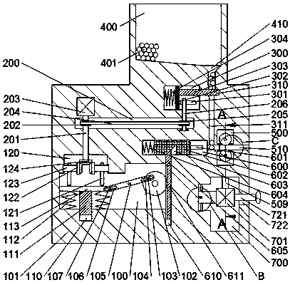
[0019] refer to Figure 1-Figure 4As shown, the projectile launching device of the present invention includes a device casing 101, a first transmission chamber 100 is arranged in the device casing 101, and a rack chute 610 is arranged in the inner bottom wall of the first transmission chamber 100, so that A rack 611 is slidably installed in the...


PUM


Abstract

The invention discloses a projectile emission device. The device comprises a device shell, a first transmission cavity is formed in the device shell, a rack sliding groove is formed in the inner bottom wall of the first transmission cavity, a rack is arranged in the rack sliding groove in a sliding fit manner, a gear is arranged in the first transmission cavity in a rotary fit manner, the gear isengaged with the rack, a first convex block is fixedly arranged on the front side end face of the gear, a connecting rod is arranged in the first transmission cavity in a rotary fit manner, a first sliding groove is arranged in the connecting rod in a penetrating manner, the first sliding groove is in sliding fit connection with the first convex block, a second sliding groove is formed in the connecting rod in a penetrating manner, a third sliding groove is formed in the inner bottom wall of the first transmission cavity, a sliding block is arranged in the third sliding groove in a sliding fitmanner, a first pressing plate is fixedly arranged on the upper end face of the sliding block, symmetric first return springs are fixedly arranged between the lower end face of the first pressing plate and the inner bottom wall of the first transmission cavity, and a second transmission cavity is formed in the inner top wall of the first transmission cavity.

Description

technical field [0001] The invention relates to the field of weapon engineering, in particular to a projectile launching device. Background technique [0002] The traditional projectile launching device has a single function, only has the most basic ejection function, and cannot increase the function of rotation. However, in various fields such as weapons and sports, the requirements for the rotation of projectiles are very high, so there is an urgent need for a compact structure and precise design. The launching device, while ensuring the most basic functions, rotates the projectile to a certain extent while ejecting, thereby improving the functionality of the device. Contents of the invention [0003] The object of the present invention is to provide a projectile launching device capable of overcoming the above-mentioned drawbacks of the prior art. [0004] According to the present invention, the projectile launching device of the present invention includes a device cas...

Claims


Application Information

Patent Timeline
Patent Type & Authority Applications(China)
IPC IPC(8): F41F1/00
CPCF41F1/00
Inventor 徐建军
Owner 徐建军
Why Eureka
Try Eureka