Automatic RFID Wafer returning device

A material return and automatic technology, applied in the direction of transportation and packaging, conveyor objects, etc., can solve the problems of unfavorable use, inconvenient, lightweight, and limited installation space of the return device

Pending Publication Date: 2021-05-14
DELONG INFORMATION TECH SUZHOU
View PDF0 Cites 0 Cited by
  • Summary
  • Abstract
  • Description
  • Claims
  • Application Information

AI Technical Summary

Problems solved by technology

[0003] The existing RFID Wafer automatic return device has certain disadvantages in use. Due to the assembly limitation of the wafer tray of the die bonder, the installation space of the return device is limited. The traditional return device is not simple a

Method used


Image

  • Automatic RFID Wafer returning device
  • Automatic RFID Wafer returning device
  • Automatic RFID Wafer returning device

Examples


Embodiment Construction

[0022] In order to make the technical means, creative features, goals and effects achieved by the present invention easy to understand, the present invention will be further described below in conjunction with specific embodiments.

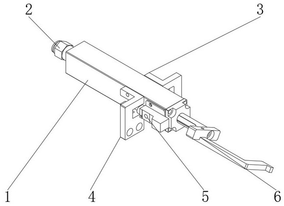
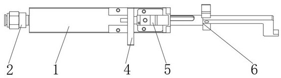
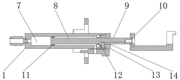
[0023] like Figure 1-4 As shown, the RFID Wafer automatic material return device includes housing 1, push-in connector 2, No. 1 mounting plate 3, No. 2 mounting plate 4, in-position sensor 5, push rod 6, lower cavity 7, upper cavity 8, guide Shaft 9, in-position block 10, seal ring 11, guide pin 12, guide pin support block 13, in-position pin 14, the quick-plug joint 2 is installed at the bottom of the housing 1, and the seal ring 11 is installed in the bottom groove of the guide shaft 9, The guide shaft 9 is installed inside the shell 1, the first mounting plate 3 and the second mounting plate 4 are installed on both sides of the shell 1, the guide pin support block 13 is installed on the top of the shell 1, and the guide shaft 9 is installed on...


PUM


Abstract

The invention discloses an automatic RFID Wafer returning device. The device comprises a shell, a quick connector, a first mounting plate, a second mounting plate, an in-place sensor, a push rod, a lower cavity, an upper cavity, a guide shaft, an in-place block, a sealing ring, a guide pin, a guide pin supporting block and an in-place pin, wherein the quick connector is installed at the bottom of the shell, the sealing ring is installed in a groove in the bottom of the guide shaft, the guide shaft is installed in the shell, the first mounting plate and the second mounting plate are mounted on the two sides of the shell, the guide pin supporting block is mounted on the top of the shell, and the guide shaft is mounted in the shell and the guide pin supporting block. According to the automatic RFID Wafer returning device, the problems are effectively solved, operation is convenient, the device can be compatible with Wafer material trays of different sizes, in this way, the use cost and the maintenance cost of a user side are effectively saved, convenience is provided for upgrading of future products, and better use prospects are brought.

Description

technical field [0001] The invention relates to the field of RFID Wafer automatic material return, in particular to an RFID Wafer automatic material return device. Background technique [0002] RFID Wafer automatic material return device is a supporting device for DDD. With the rapid development of the RFID industry, there are more and more types of chips, and the types of die bonders are also increasing. The efficiency improvement has become a The important competitive advantage of the machine, the improvement of the chip removal efficiency is of great help to the improvement of the overall efficiency of the die bonder. With the continuous development of technology, people have higher and higher requirements for the manufacturing process of the RFID Wafer automatic material removal device. [0003] The existing RFID Wafer automatic return device has certain disadvantages in use. Due to the assembly limitation of the wafer tray of the die bonder, the installation space of th...

Claims


Application Information

Patent Timeline
IPC IPC(8): B65G47/82
CPCB65G47/82
Inventor 陈龙王睿张辉郁文新
Owner DELONG INFORMATION TECH SUZHOU
Why Eureka
Try Eureka