Cross girder structure integrated loading system

A technology of structural synthesis and loading system, which is applied in measurement devices, instruments, scientific instruments, etc., and can solve the problem of inability to simulate the working conditions of multiple loads at the same time

Pending Publication Date: 2018-12-04
上海筑邦测控科技有限公司
View PDF0 Cites 2 Cited by
  • Summary
  • Abstract
  • Description
  • Claims
  • Application Information

AI Technical Summary

Problems solved by technology

However, this loading method has certain limitations and cannot simulate the simultaneous acti...

Method used


Image

  • Cross girder structure integrated loading system
  • Cross girder structure integrated loading system
  • Cross girder structure integrated loading system

Examples


Embodiment 1

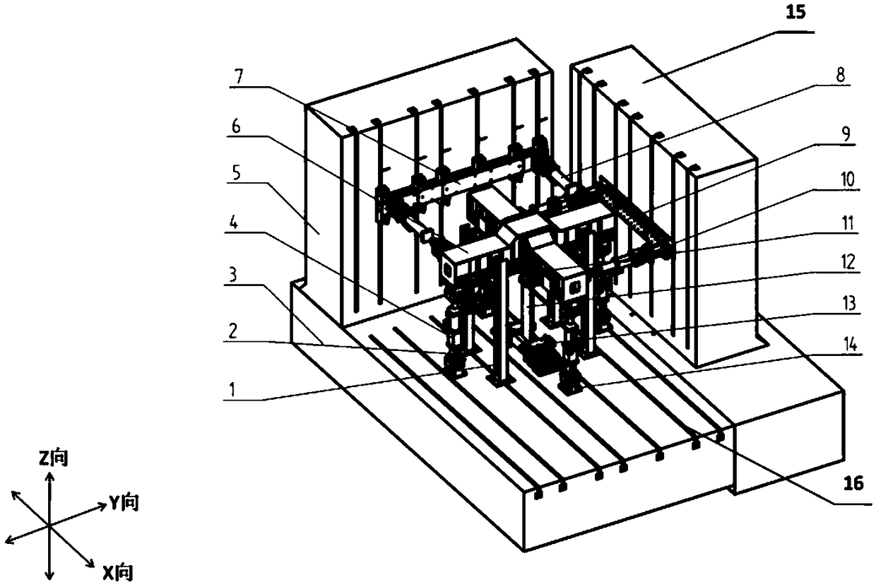
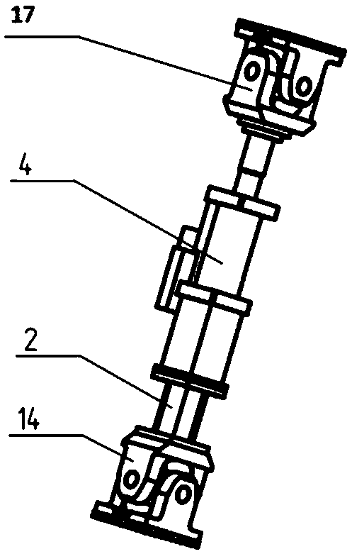
[0040] Such as figure 1 As shown, the comprehensive loading system of the cross main beam structure of the present embodiment includes: reaction force platform 3, X direction reaction force wall 15, Y direction reaction force wall 5, cross main beam 6, tooling accessories, four Z direction Actuator 4, two X-direction actuators 8, two Y-direction actuators 10, X-direction actuator mount 7, Y-direction actuator mount 9, support structure 1, etc.

[0041] Wherein, the reaction force platform 3 is placed on a horizontal plane. The reaction platform 3 , the X-direction reaction wall 15 and the Y-direction reaction wall 5 are arranged perpendicular to each other. In this embodiment, there is no special limitation on the structures of the reaction wall and the reaction platform. For example, the two kinds of reaction walls 5 and 15 can be either civil structures or steel frame structures. The reaction force platform 3 can be either a civil structure or a steel frame structure.

...


PUM


Abstract

The invention discloses a cross girder structure integrated loading system. The system comprises a reaction platform, an X-direction reaction wall, a Y-direction reaction wall, a cross girder, a tooling attachment, four Z-direction actuators, two X-direction actuators and two Y-direction actuators. A test piece is mounted in the tool attachment, the top end of each Z-direction actuator is movablyconnected with the corresponding end part of the cross girder, the bottom end of each Z-direction actuator is movably connected with the reaction force platform, one end of each X-direction actuator is movably connected with the Y-direction corresponding end part of the cross girder, the other end of each X-direction actuator is movably connected with the Y-direction reaction wall, one end of eachY-direction actuator is movably connected with the X-direction corresponding end part of the cross girder, and the other end of each Y-direction actuator is movably connected with the X-direction reaction wall. Two ends of the three actuators are movably connected with other structures, so the simultaneous acting condition of multiple loads can be simulated, thereby multi-degree-of-freedom loading is achieved.

Description

technical field [0001] The invention belongs to the technical field of civil engineering structure test loading systems, and relates to a comprehensive loading system for cross main beam structures. Background technique [0002] The conventional loading method of the currently known civil engineering structure test loading system (especially the civil engineering compression-shear test loading system) is: a vertical actuator is arranged vertically to simulate the gravity load, and a horizontal actuator is arranged horizontally to simulate the gravity load. To simulate shear force, two actuators simultaneously load the specimen. However, this loading method has certain limitations and cannot simulate the simultaneous action of multiple loads. Therefore, a loading system that can realize multi-degree-of-freedom loading is needed. Contents of the invention [0003] Aiming at the deficiencies of the prior art, the present invention provides a comprehensive loading system for ...

Claims


Application Information

Patent Timeline
IPC IPC(8): G01N3/02
CPCG01N3/02G01N2203/0272G01N2203/0435
Inventor 戈锐胡敬礼胡电锋曾庆民
Owner 上海筑邦测控科技有限公司
Why Eureka
Try Eureka