Multiple degree of freedom substrate manipulator

a manipulator and multi-degree technology, applied in the direction of motor/generator/converter stopper, dynamo-electric converter control, instruments, etc., can solve the problems of increased force, loss of planarity of wafer or substrate, and warpage of the chuck surfa

Inactive Publication Date: 2004-06-29
ACTIVE PRECISION
View PDF3 Cites 52 Cited by
  • Summary
  • Abstract
  • Description
  • Claims
  • Application Information

AI Technical Summary

Benefits of technology

According further to the present invention, an apparatus for manipulation of a substrate includes a handler that holds the substrate, a housing that holds the handler, and a plurality of actuators that move the handler in response to at least one control signal, where the plurality of actuators further includes at least one high frequency actuator and at least one low frequency actuator that provide motion in a single direction and wherein the at least one control signal includes a high frequency portion that is provided to the at least one high frequency actuator and a low frequency portion that is provided to the at least one low frequency actuator. The at least one low frequency actuator may reduce static forces on the at least one high frequency actuator. The at least one low frequency actuators may include at least one radial electromagnet. The at least one high frequency actuator may include at least one tangential electromagnet. The at least one low frequency actuator may be a pneumatic actuator. The pneumatic actuator may actuate the handler in a vertical direction. The at least one high frequency actuator may include an electromagnetic actuator that provides a force in a vertical direction on the handler.
According further to the present invention, a substrate manipulator providing control of movements in the Z, roll, pitch and yaw directions, includes a housing, a surface handler disposed in the housing, at least one hub, disposed concentric to a center point of the housing and free to rotate about the Z axis using at least three magnetically preloaded air bearing regions located between the housing and the hub, a pair of magnetically preloaded bearings that constrain the hub to rotate substantially about the axis of the housing, at least three tangential voice coil motors that provide a yaw moment without creating any substantial XY force on the hub relative to the housing, and at least three Z actuators to move the surface handler with respect to the hub.
The stiffness of the air bearing to piston assembly is influenced by the operating pressure and circumference of the air-bearing sleeve. A larger sleeve will yield greater stiffness for the same fluid pressure supplied to the air bearing. Greater stiffness is preferred in order to enhance precision of the manipulator.

Problems solved by technology

On the other hand, the strain placed upon the chuck by the flattening action of the vacuum may result in warpage of the chuck surface, and consequent loss of planarity of the wafer or substrate.
However, increasing the mass of the chuck results in increased force necessary to move the chuck, and consequently increases stage mass and motor power levels.
Mechanical approaches to a wafer chuck become more difficult as the mass of the chuck increases and the precision requirements become more severe.
Thus, as the chuck mass increases and the bearing mass increases, the size of the actuator and the actuator power must also increase, resulting in increased power dissipation and local heating of the wafer.
Heating of the wafer may be a problem because expansion of the wafer results in a shifting of the location of different parts of the wafer, and thus loss of precision and repeatability.
The different coefficients of thermal expansion of the aluminum (or other material) chuck and the semiconductor wafer may also result in mismatched stress between the chuck and the wafer, and may result in wafer warpage.
Thus, power dissipation in the actuators of the chuck may lead to thermal gradients and corresponding changes in the mechanical dimensions of the chuck mechanism, which may be another major impediment to achieving the levels of precision required in many semiconductor processes, liquid crystal display processes, thin film magnetic head processes, and micro-machining processes.
While these devices provide large forces with negligible heat generation, they are unable to provide sufficient range of motion to allow wafer transfers between a transfer robot and the chuck.
Contact with the front surface of the wafer may result in physical damage such as scratching, and may also result in contamination of the devices on the front surface.
This additional requirement of piezo actuators increases the cost, complexity, and the mass of the stage.
Another problem with mechanical methods of moving a wafer chuck around, such as the piezo actuators, is that the physical contact of the piezo actuators with the chuck may represent another source of stress and strain, and therefore cause deformation of the chuck and resulting loss of precision.
As noted before, certain manufacturing processes, such as semiconductor device manufacture, liquid crystal display manufacture, and thin film magnetic head manufacture, require extreme flatness in the manufactured device, and consequently extreme flatness in the chuck.
Since the power dissipation increases with the square of the total stage mass, a small increase in mass may result in a large increase in power consumption.
The heat dissipated by the stage influences the stage accuracy and precision due to thermal disturbance of the air inside a tool, since the thermal gradients disrupt the precision of the distance measuring laser interferometers that are typically used to measure the location of the stage.
Changes in heat dissipation also affect the precision of the interferometer, and thus the repeatability of the operation.
However it has been previously noted that it is difficult to have high precision and large motion simultaneously.
This causes increased time, cost, size and heat dissipation of the stage.
A well known problem with fluid control systems is the level of noise that is often injected in to the pressure chamber due to turbulence in the servo valve.
The turbulence in the fluid creates minute pressure disturbances that may be apparent as a source of noise making nanometer-level of precision difficult to achieve.

Method used


Image

  • Multiple degree of freedom substrate manipulator
  • Multiple degree of freedom substrate manipulator
  • Multiple degree of freedom substrate manipulator

Examples


Embodiment Construction

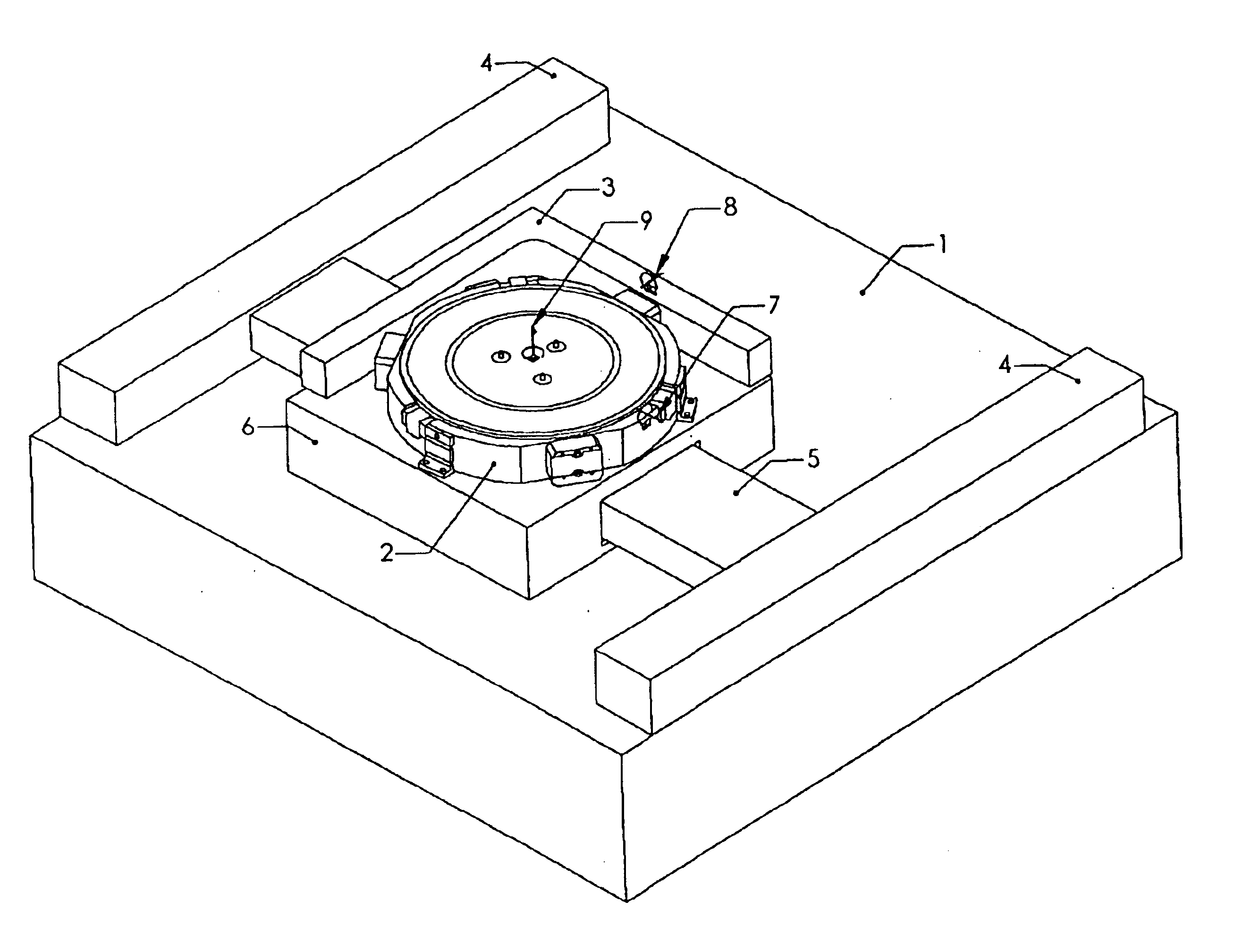
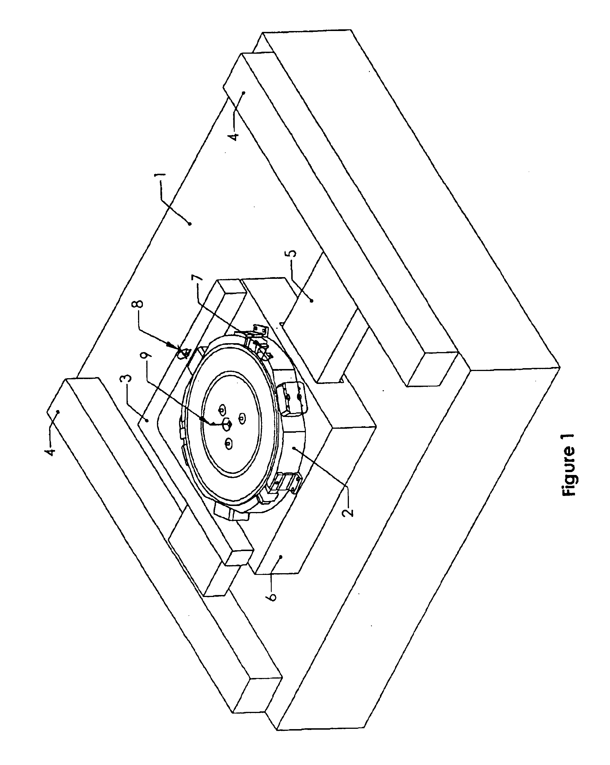
With reference to FIG. 1, shown is an isometric view of an XY stage 1 with the chuck and housing mechanism 2 mounted on the stage. The basic elements of the XY stage would be easily recognized by those skilled in the art as the dual Y-axis drives 4, a single X axis drive 5 which together drive the slider 6 and whose position is typically monitored by an interferometer (not shown) that monitors slider position via L-shaped interferometer mirror 3. The stage is not part of the present invention. It is shown merely for illustrative purposes.

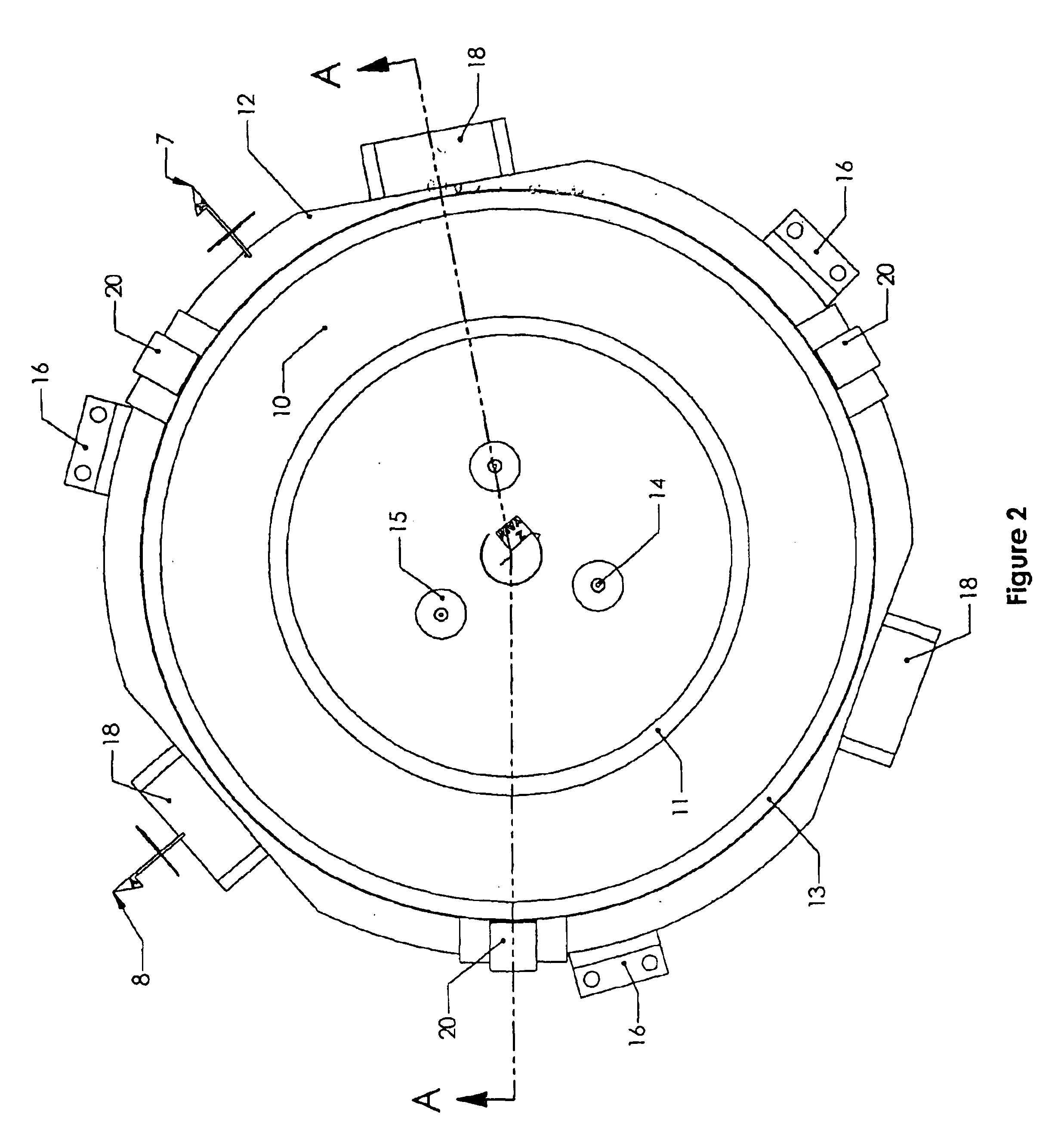
With reference to FIG. 2, shown is a top view of the substrate holder 10, supported by a housing 12 which substantially surrounds the sides and bottom of the substrate holder 10, and carries the substrate holder 10 in a plane on an XY stage 1. The substrate holder 10 has three wafer or substrate lift pins 14, each of which has a central hollow for connection to a vacuum pressure line for securing the wafer or substrate to the pins when the surface h...


PUM

PropertyMeasurementUnit
diameteraaaaaaaaaa
diameteraaaaaaaaaa
diametersaaaaaaaaaa

Abstract

A system for manipulating a planar substrate such as a semiconductor wafer is provided. The manipulator is typically used in conjunction with an XY stage to focus and planarize a wafer with respect to a tool. The manipulator employs redundant actuators of different types and a control system that uses low-bandwidth, high efficiency actuators to provide low frequency forces and high-bandwidth, but less efficient, actuators to provide all other forces. The manipulator provides support and manipulation of a substrate while minimizing errors due to thermal distortion.

Description

1. Technical FieldThis application relates to handling substrates, and more particularly to handling of a substrate with control over an operating range spanning a minimum of three and a maximum of six degrees of freedom.2. Description of Related ArtSubstrate handling mechanisms are often used in equipment designed to process semiconductor wafers, flat screen liquid crystal displays, printed circuit boards, and micromachine assemblies. Similar mechanisms are used in failure analysis systems, electrical and functional testing systems, and IC packaging systems.Modern semiconductor wafers may be cylindrical substrates of silicon, up to 300 mm in diameter, and may be less than 1 mm thick. During many of the manufacturing processes of semiconductor devices, wafers are held on a substrate holder known as a chuck, using vacuum. The chuck is often also used as a substrate handler, to position the substrate at a specified location in up to six dimensions, and to move the substrate from an in...

Claims


Application Information

Patent Timeline
Patent Type & Authority Patents(United States)
IPC IPC(8): G03F7/20
CPCG03F7/707G03F7/70758G03F7/70858Y10T74/20348Y10T74/20341
Inventor HUNTER, BRADLEY L.
Owner ACTIVE PRECISION
Why Eureka
Try Eureka