
Method for recovering wave surface with high precision based on single width interference fringe

An interference fringe, high-precision technology, applied in measurement devices, instruments, optical devices, etc., can solve problems such as complex algorithms, complex hardware, algorithms, and inability to correctly determine the direction of wave surface concave and convex, and achieve the effect of simple calculation

Active Publication Date: 2018-12-07
JIANGNAN UNIV
View PDF6 Cites 9 Cited by
  • Summary
  • Abstract
  • Description
  • Claims
  • Application Information

AI Technical Summary

Problems solved by technology

[0006] In order to solve the existing problems of complex algorithms, limited application conditions, and the inability to correctly determine the direction of the wave surface concave and convex, the present invention provides a method for recovering the wave surface with high precision based on a single interference fringe
This method overcomes the problems that the interferometric system requires high-precision phase shifter hardware and complex algorithms. By dividing the interference fringes into areas, the pixels of the interferometer cameras in the same area have the same parity, so that accurate phase extraction can be performed.

Method used


Image

  • Method for recovering wave surface with high precision based on single width interference fringe
  • Method for recovering wave surface with high precision based on single width interference fringe
  • Method for recovering wave surface with high precision based on single width interference fringe

Examples


Embodiment 1

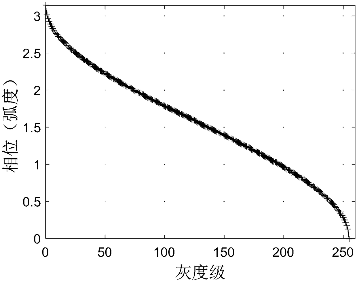
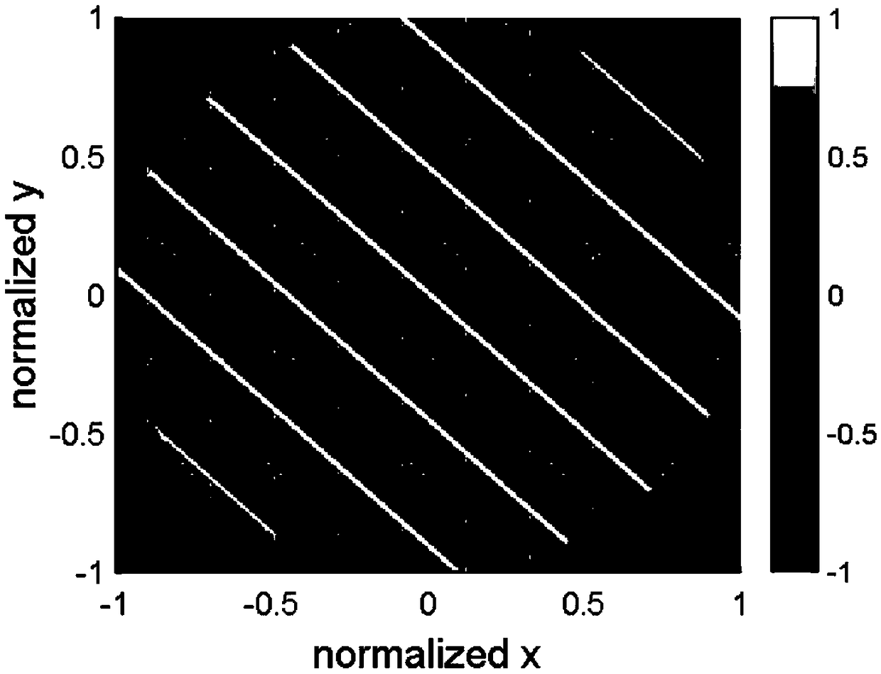
[0089] A method for recovering wavefronts from a single interference fringe with high precision, including: building an optical path, collecting a single interferogram, regularizing the interference fringes, calculating the peak-to-valley values ​​of the interference fringes, dividing regions according to the peak-to-valley values, and classifying different Area pixel assignment, convert the light intensity into a phase from 0 to π, then convert the phase from 0 to π into a phase from 0 to 2π according to the value assigned by the pixel, and then unwrap the phase from 0 to 2π, unwrap the Zernike polynomial fitting is performed on the phase of the phase, and finally the fitting result is halved to obtain the final measurement result of the surface shape of the optical element.

[0090] 1. Build the light path:

[0091] Figure 4Schematic diagram of the optical path for measuring the surface shape of optical components by the interferometer method, using Daheng's GCI-0601 DC vo...


PUM


Abstract

The invention discloses a method for recovering a wave surface with high precision based on a single width interference fringe and belongs to the field of surface shape measurement of optical components. The method includes the following steps: peak values and valley values are assigned in an interference region so as to convert the same into phases, the interference fringe is divided into regions, pixels of interferometer cameras in the same region are enabled to be the same in parity, and accurate phase extraction is performed to achieve high-precision wave surface recovery. According to themethod disclosed in the invention, the peak values and the valley values are assigned in the interference region so as to convert the same into phases, the interference fringe is divided into the regions, the pixels of the interferometer cameras in the same region are enabled to be the same in parity, and accurate phase extraction is performed to achieve high-precision wave surface recovery. Themethod is simple and efficient in calculation, no carrier frequency function is needed, and neither Fourier transform nor Hilbert transform is required.

Description

technical field [0001] The invention relates to a method for recovering a wave surface with high precision based on a single interference fringe, which belongs to the field of surface shape measurement of optical elements. Background technique [0002] At present, optical elements such as optical lenses, plane mirrors, spherical mirrors, aspheric mirrors, and free-form surface mirrors are widely used in optical systems such as optical telescopes, space cameras, and video cameras. In order to meet the resolution and other indicators of the imaging system, the surface shape accuracy requirements of these optical components are very strict. Therefore, in the process of processing, it is necessary to perform surface shape detection on these optical components; in practical applications, the interferometric method is surface shape detection. One of the most widely used means in Interferometry can be further divided into two measurement methods: sub-amplitude and sub-wave surface...

Claims


Application Information

Patent Timeline
Patent Type & Authority Applications(China)
IPC IPC(8): G01B11/25
Inventor 胡立发胡栋挺申文刘新宇马文超
Owner JIANGNAN UNIV
Learn More