Electronic automation cutting device

A cutting device and electronic technology, applied in the direction of large fixed members, metal processing machine parts, metal processing, etc., can solve the problems of large error, position deviation, and easy shaking of cutting materials, etc., and achieve the effect of easy promotion and simple structure

Inactive Publication Date: 2018-12-14
HEFEI CANGMIN AUTOMATION CO LTD
View PDF0 Cites 3 Cited by
  • Summary
  • Abstract
  • Description
  • Claims
  • Application Information

AI Technical Summary

Problems solved by technology

With the continuous development of steel products, the quality and precision requirements of automatic cutting are also constantly improving. Most of the existing cutting machines use manual direct push to cut materials, and use cutting knives for cutting. Due to the texture of many materials Harder, when the cutting knife is cutting, the cutting material is prone to shaking and position deviation, which affects the accuracy of steel material cutting. When cutting steel pipes of different lengths, most of them are measured by eye or movable ruler, and the error is large, so As a result, the parts cannot be used and a lot of resources are wasted. There are certain safety hazards in the manual operation of the cutting machine, and the cutting knives of the cutting machine cannot be controlled with high precision.

Method used


Image

  • Electronic automation cutting device
  • Electronic automation cutting device
  • Electronic automation cutting device

Examples


Embodiment Construction

[0019] The following will clearly and completely describe the technical solutions in the embodiments of the present invention with reference to the accompanying drawings in the embodiments of the present invention. Obviously, the described embodiments are only some, not all, embodiments of the present invention. All other embodiments obtained by persons of ordinary skill in the art based on the embodiments of the present invention belong to the protection scope of the present invention.

[0020] According to an embodiment of the present invention, an electronic automatic cutting device is provided.

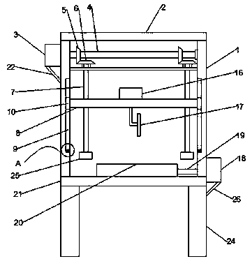
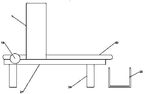
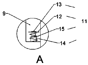
[0021] like Figure 1-3 As shown, the electronic automatic cutting device according to the embodiment of the present invention includes a cutting bracket 1, the upper end of the cutting bracket 1 is provided with a cover plate 2, and the upper end of one side of the cutting bracket 1 is provided with a motor one 3, and the motor One end of a 3 is provided with a rotating shaft 4 ...


PUM


Abstract

The invention discloses an electronic automation cutting device. The electronic automation cutting device comprises a cutting support, wherein a motor I is arranged at the upper end of one side of thecutting support; a rotating shaft I is arranged at one end of the motor I; rotating gears are arranged at the two ends of the rotating shaft I; linkage gears are arranged at the lower ends of the rotating gears; threaded rods are arranged at the lower ends of the middle parts of the linkage gear; a lifting plate is arranged at the middle parts of the threaded rods; buffer devices are arranged atthe lower ends of sliding chutes; a transverse plate is arranged at the upper end of each buffer device; an expansion link is arranged at the lower end of the transverse plate; a spring is arranged onthe exterior of the expansion link in a sleeving manner; a motor II is arranged at the upper end of the middle part of the lifting plate; a cutting device is arranged at the lower end of the liftingplate; a motor III is arranged on the cutting support; and a conveying device is arranged at one end, far away from the motor III, of a rotating shaft II. The electronic automation cutting device hasthe beneficial effects of electronic automation cutting, simple structure and convenient popularization.

Description

technical field [0001] The invention relates to the field of electronic automation, in particular to an electronic automatic cutting device. Background technique [0002] Electronic automatic cutting machine is widely used in petroleum, chemical industry, electric power, natural gas, metallurgy, shipbuilding, boiler, pharmaceutical, water treatment and other industries, as well as pipeline installation engineering and pipeline maintenance of new projects. With the continuous development of steel products, the quality and precision requirements of automatic cutting are also constantly improving. Most of the existing cutting machines use manual direct push to cut materials, and use cutting knives for cutting. Due to the texture of many materials Harder, when the cutting knife is cutting, the cutting material is prone to shaking and position deviation, which affects the accuracy of steel material cutting. When cutting steel pipes of different lengths, most of them are measure...

Claims


Application Information

Patent Timeline
Patent Type & Authority Applications(China)
IPC IPC(8): B23D79/00B23Q1/25B23Q7/00
CPCB23D79/00B23Q1/25B23Q7/00
Inventor 王泽春徐群
Owner HEFEI CANGMIN AUTOMATION CO LTD
Why Eureka
Try Eureka