Ultrasonic tight oil imbibition experimental device

An experimental device and technology for tight oil, applied in wellbore/well components, construction, production fluids, etc., can solve problems such as inability to observe imbibition fronts intuitively, difficulty in measuring produced crude oil, and experimental errors.

Active Publication Date: 2019-11-12
CHINA UNIV OF PETROLEUM (BEIJING) +2
View PDF12 Cites 0 Cited by
  • Summary
  • Abstract
  • Description
  • Claims
  • Application Information

AI Technical Summary

Problems solved by technology

[0003] At present, the relevant research on oil displacement in tight reservoirs mainly takes laboratory cores as the research object. For example, invention CN107101925A and invention CN104020098A are small-scale core imbibition experiments, but the disadvantages of core experiments are obvious. In the scene of water immersion, soaking the core directly in water at the same time will easily cause the capillary force to offset, resulting in experimental errors. In addition, the core imbibition experiment makes it difficult to measure the produced crude oil, and the imbibition front cannot be directly observed, nor can it simulate the actual storage. process of imbibition under pressure
The core displacement device using nuclear magnetic resonance and other technologies, such as the invention CN106908470A, can realize the occurrence and flow of fluid in the core through nuclear magnetic technology, but the imbibition is a phenomenon that occurs along the direction of capillary force, and the direction of capillary force And the microchannel inside the core is controlled, so the direction of imbibition can be in any direction, but this invention uses rubber sleeves and adds confining pressure to block the core cylinder, leaving only the end face of the core, which obviously affects the occurrence of imbibition

Method used


Image

  • Ultrasonic tight oil imbibition experimental device
  • Ultrasonic tight oil imbibition experimental device
  • Ultrasonic tight oil imbibition experimental device

Examples


Embodiment Construction

[0049] In order to have a clearer understanding of the technical features, purposes and effects of the present invention, the specific implementation manners of the present invention will now be described with reference to the accompanying drawings.

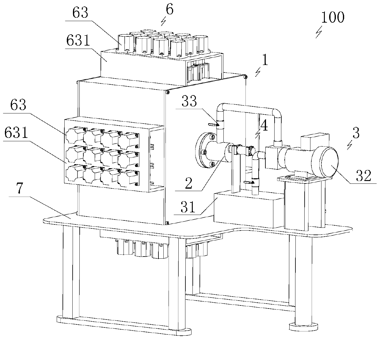
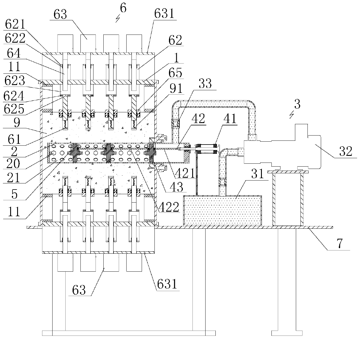
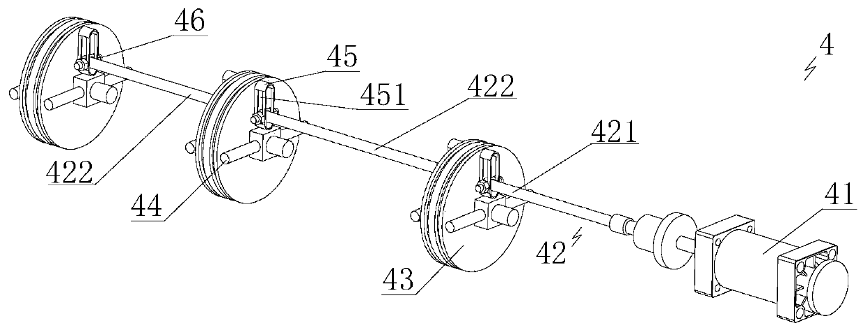
[0050] Such as Figure 1 to Figure 4 As shown, the present invention provides an ultrasonic tight oil imbibition experimental device 100, which includes a rock fixing box 1 for sealing and containing tight oil rock 9, and the cross sections of the rock fixing box 1 and tight oil rock 9 are arranged in a rectangular shape ; One side of the rock fixing box 1 is sealed and pierced with a fracturing pipe 2 that can be pierced in the tight oil rock 9, and a horizontal center hole is drilled on the tight oil rock 9, and the fracturing pipe 2 is pierced in the In the central hole, in a specific embodiment of the present invention, one side of the rock fixing box 1 is provided with a fracturing tube through hole, and the fracturing tube ...


PUM


Abstract

The invention relates to an ultrasonic tight oil imbibition experiment device comprising a rock fixed box; a fracture pipe capable of penetrating a tight coil rock penetrates one side of the rock fixed box in a sealed manner, and the other end of the fracture pipe is connected with a fracture liquid injection structure in a foldable manner; a push structure penetrates the fracture pipe in a sealedand slide manner, and provided with a plurality of ultrasonic probes; the side wall, on which the fracture pipe penetrates, of the rock fixed box is the first fixed box side wall; each side wall adjacent to the first fixed box side wall on the rock fixed box is provided with a telescopic potential resistance imbibition test structure; the ultrasonic tight oil imbibition experiment device also comprises a control portion; the control portion can control the work states of the fracture liquid injection structure, the push structure and the potential resistance imbibition test structure. The device can test oil-water replacement rate and oil extraction effects of fracture liquids of different formulas, can analyze the pressure propagation speed and oil-water replacement leading edge positionin the imbibition process, thus providing important meanings for selecting and optimizing and evaluating soak effects of fracture liquids of different formulas.

Description

technical field [0001] The invention relates to the technical field of oil and gas exploitation, in particular to an ultrasonic tight oil imbibition experimental device. Background technique [0002] Tight oil resources are extremely abundant at home and abroad. Although it has been commercially exploited in the United States, Canada and other countries, in China, due to the poor physical properties of tight oil reservoirs and insufficient natural energy, the effect of depletion mining is not ideal. Water injection, gas injection huff and puff, etc. Mining methods also have their own limitations. For tight oil reservoirs, since crude oil is accumulated in the rock pore structure with a permeability of less than 0.1 mD, its economical and efficient development depends on horizontal drilling and multi-stage hydraulic fracturing technology. When performing hydraulic fracturing operations on horizontal wells, tens of thousands of cubic meters of fracturing fluid are pumped int...

Claims


Application Information

Patent Timeline
Patent Type & Authority Patents(China)
IPC IPC(8): E21B43/26E21B47/107
CPCE21B43/26E21B47/107
Inventor 周福建左洁梁天博姚二冬李奔许江文罗兆郭新维承宁怡宝安袁峰吕述奇
Owner CHINA UNIV OF PETROLEUM (BEIJING)
Why Eureka
Try Eureka