Automatic film sticking machine

A laminating machine, automatic technology, applied in the direction of electrical components, coupling devices, circuits, etc., can solve problems such as poor stability, unexpected power failure, electric shock accidents, etc., to improve stability and safety, improve electricity safety, prevent Effects of electric shock accidents

Inactive Publication Date: 2018-12-18
广州创码信息科技有限公司
View PDF6 Cites 0 Cited by
  • Summary
  • Abstract
  • Description
  • Claims
  • Application Information

AI Technical Summary

Problems solved by technology

[0002] With the continuous development of industrial technology, some automatic film laminating machines are widely used in industrial production. These automatic film laminating machines need to be connected to the mains when they work. However, the traditional power supply device for these automatic film laminating machines has a setting mode Relatively simple, its internal c

Method used


Image

  • Automatic film sticking machine
  • Automatic film sticking machine

Examples


Example Embodiment

[0019] All the features disclosed in this specification, or all disclosed methods or steps in the process, except for mutually exclusive features and / or steps, can be combined in any manner.

[0020] Any feature disclosed in this specification (including any appended claims, abstract and drawings), unless specifically stated, can be replaced by other equivalent or alternative features with similar purposes. That is, unless otherwise stated, each feature is just one example of a series of equivalent or similar features.
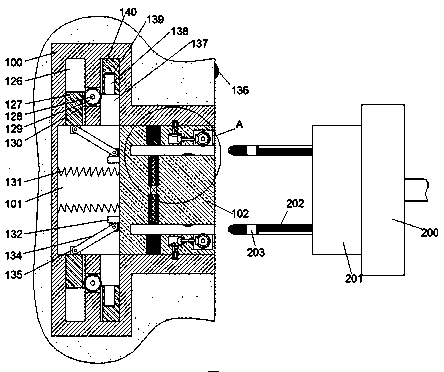
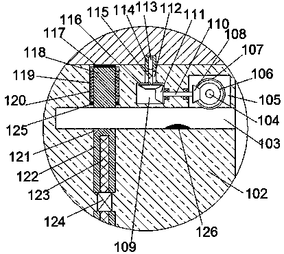
[0021] Such as Figure 1-2 As shown, an automatic film sticking machine of the device of the present invention includes an electrical connector 100 fixed in a wall and an electrical connector 200 connected to the film machine. The electrical connector 100 is provided with a rightward sliding slot. The sliding cavity 101, in which a sliding frame 102 is slidably installed, the sliding frame 102 is symmetrically provided with an insertion slot 103 with a rightward n...


PUM


Abstract

The invention discloses an automatic film sticking machine, which comprises an electric connecting seat fixed in a wall body and an electric connecting head connected with a film pasting machine, thecoupler seat is provided with a sliding cavity with a notch facing to the right, A sliding frame is slidably installed in the sliding cavity, the sliding frame is symmetrically provided with an insertion groove with a notch facing to the right, A first sliding groove is symmetrically arranged in the upper and lower two end walls inserted into the inner side of the groove, A first sliding block isslidably mounted in the first sliding groove, A first screw-shaped hole is arranged in the first sliding block, A first screw-shaped rod is fitted and installed in the first screw-shaped hole, A motoris fixed in the sliding frame between the upper and lower first sliding grooves, At least one of that upper and low inner end of the first screw rod is respectively dynamically connected with the upper and lower end faces of the motor, A second sliding groove is arranged in the end wall of the insertion groove which is far away from the first sliding groove, a second sliding block is slidably installed in the second sliding groove, and a first conductive head is fixed on the end surface of the second sliding block which is far away from the first sliding groove.

Description

technical field [0001] The invention relates to the technical field of film laminating machines, in particular to an automatic film laminating machine. Background technique [0002] With the continuous development of industrial technology, some automatic film laminating machines are widely used in industrial production. These automatic film laminating machines need to be connected to the mains when they work. However, the traditional power supply device for these automatic film laminating machines has a setting mode Relatively simple, its internal conductive sheet is connected with the outside, human accidental contact will cause electric shock accidents, there is a great potential safety hazard, at the same time, the existing automatic film laminating machine has poor stability when power supply connection, often causing Unexpected power failure occurs due to loose plug connection, which brings great changes to normal use. Contents of the invention [0003] Aiming at the...

Claims


Application Information

Patent Timeline
IPC IPC(8): H01R13/633H01R13/635H01R13/639H01R13/70
CPCH01R13/633H01R13/635H01R13/639H01R13/701
Inventor 钟奇
Owner 广州创码信息科技有限公司
Why Eureka
Try Eureka