
Electronic lock cylinder controlled independently through electronic keys on both sides

An independent control, electronic key technology, applied in the field of locks, can solve the problems of sabotage, anti-drilling and low security, and locks cannot be anti-violence, and achieve the effect of preventing violent damage

Pending Publication Date: 2018-12-21
YANGZHOU ANXINZHI TECH CO LTD
View PDF0 Cites 0 Cited by
  • Summary
  • Abstract
  • Description
  • Claims
  • Application Information

AI Technical Summary

Problems solved by technology

[0003] The purpose of the present invention is to provide an electronic lock cylinder independently controlled by electronic keys on both sides, which solves the technical problems that the locks in the prior art cannot be anti-violent damage, anti-drilling and low security

Method used


Image

  • Electronic lock cylinder controlled independently through electronic keys on both sides
  • Electronic lock cylinder controlled independently through electronic keys on both sides
  • Electronic lock cylinder controlled independently through electronic keys on both sides

Examples


Embodiment 1

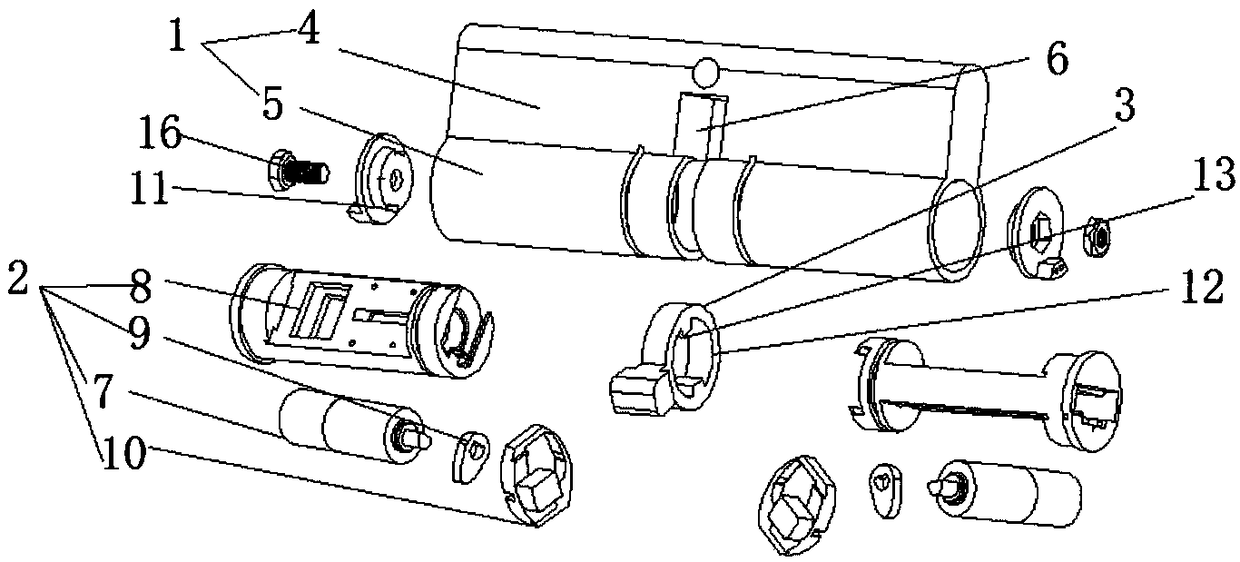
[0022] Such as Figure 1-2 As shown, an electronic lock cylinder independently controlled by electronic keys on both sides provided by the present invention includes a housing 1, two lock cylinder mechanisms 2 and dial tongues 3, and the lock cylinder mechanisms 2 are arranged at intervals inside the housing 1. The dial tongue 3 is arranged between the lock cylinder mechanisms 2 , and the dial tongue 3 is connected with the lock cylinder mechanism 2 .

[0023] Wherein, the housing 1 includes a solid part 4 and two hollow parts 5, the solid part 4 is provided with a dial tongue groove 6, the hollow part 5 is arranged below the solid part 4 at intervals, the tongue dial groove 6 and the The gap between the two hollow parts 5 corresponds, the dial tongue 3 is arranged between the hollow parts 4, and the lock cylinder mechanism 2 is arranged inside the hollow part 5, and the existing mechanical lock is usually inside the shell There will be a pin structure, but it is easy to be d...

Embodiment 2

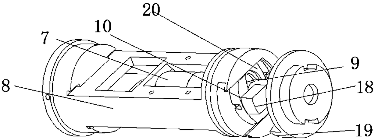
[0028] Such as image 3 As shown, based on Embodiment 1, in the present invention, a clutch groove 17 is provided at the end of the lock core 8, the clutch block 10 is arranged inside the clutch groove 17, and a groove 18 is provided inside the clutch block 10, and the clutch block 10 is provided with a groove 18. The cam 9 is located inside the groove 18, the driving device 7 pushes the cam 9 to rotate, the cam 9 drives the clutch block 10 to move along the clutch groove 17, and the driving device 7 is a motor;

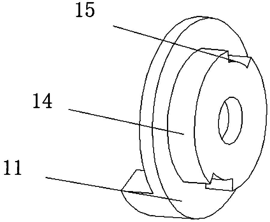
[0029] Wherein, the clutch block 10 is provided with a block 18, and the inner side of the tongue bracket 11 is provided with a toggle block 19, the block 18 corresponds to the toggle block 19, and the outer surface of the clutch groove 17 is opened There are grooved through holes 20, the two sides of the clutch block 10 are stepped surfaces, and the step surface is used to facilitate the movement of the clutch block 10 in the clutch groove 17, while the grooved thro...


PUM


Abstract

The invention discloses an electronic lock cylinder controlled independently through electronic keys on both sides. The electronic lock cylinder comprises a shell, two lock cylinder mechanisms and a shifting tongue, wherein the lock cylinder mechanisms are arranged inside the shell at intervals, and the shifting tongue is arranged between the lock cylinder mechanisms and connected with lock cylinder mechanisms. According to the electronic lock cylinder, the problems that in the prior art, locks cannot resist violent damage and drilling and are low in safety are solved, and the lock cylinder isindeed suitable for a security door.

Description

technical field [0001] The invention relates to the technical field of locks, in particular to an electronic lock cylinder independently controlled by electronic keys on both sides. Background technique [0002] Most of the locks currently on the market are mechanical locks, and the tongue used in the mechanical lock is controlled by the key between the lock head and the chain. When the key is inserted into the lock head, the other end pushes out the key tongue to move. There is a bigger security risk in such a linkage relationship, because once the lock head is damaged by external force, it can be rotated freely after losing its password function, and the dial tongue will rotate together with the lock head to open or close the door lock at will. This will bring property loss to the user, even endanger the safety of life, and if one end forgets to pull out the key, the other end cannot insert the key, which will affect the customer to unlock. Contents of the invention [...

Claims


Application Information

Patent Timeline
Patent Type & Authority Applications(China)
IPC IPC(8): E05B47/00
CPCE05B47/00
Inventor 赵霄骁
Owner YANGZHOU ANXINZHI TECH CO LTD
Learn More