Bone density display method, device and apparatus

A bone density and bone technology, applied in the field of medical image processing, can solve the problems of inability to display bone density, and the display method is not intuitive enough.

Inactive Publication Date: 2018-12-21
NEUSOFT MEDICAL SYST CO LTD
View PDF5 Cites 8 Cited by
  • Summary
  • Abstract
  • Description
  • Claims
  • Application Information

AI Technical Summary

Problems solved by technology

[0003] However, the above method of displaying the T value and Z value of bone density in tabular form can only reflect the bone density of the subjec

Method used


Image

  • Bone density display method, device and apparatus
  • Bone density display method, device and apparatus
  • Bone density display method, device and apparatus

Examples


Embodiment Construction

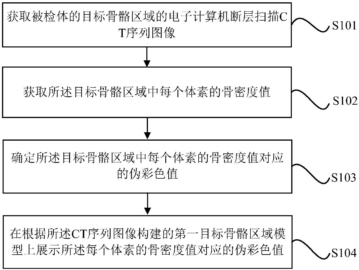
[0120] The present invention will be described in detail below in conjunction with specific embodiments shown in the accompanying drawings. However, these embodiments do not limit the present invention, and structural, method, or functional changes made by those skilled in the art based on these embodiments are included in the protection scope of the present invention.

[0121] The terminology used herein is for the purpose of describing particular embodiments only and is not intended to be limiting of the invention. As used herein and in the appended claims, the singular forms "a", "the", and "the" are intended to include the plural forms as well, unless the context clearly dictates otherwise. It should also be understood that the term "and / or" as used herein refers to and includes any and all possible combinations of one or more of the associated listed items.

[0122] It should be understood that although the terms first, second, etc. may be used in the present invention t...


PUM


Abstract

The invention discloses a bone density display method, a device and a device. The method comprises the following steps: acquiring a CT sequence image of a target bone region of a subject; Acquiring abone density value of each voxel in the target bone region; Determining a pseudo color value corresponding to a bone density value of each voxel in the target bone region; A pseudocolor value corresponding to the bone density value of each voxel is displayed on a first target bone region model constructed from the CT sequence images. The invention can more vividly display the bone density value ofeach part in the target skeleton area, and can display the change of the bone density value through the pseudo color value change of each part in the model, and the display effect is more intuitive.

Description

technical field [0001] The invention relates to the technical field of medical image processing, in particular to a bone density display method, device and equipment. Background technique [0002] In the existing bone density measurement technology, the T value and Z value of the bone density of the subject's target bone region (such as the lumbar spine, the femoral head to the femoral neck, etc.) are generally displayed in the form of a table. Among them, T is the ratio of the average bone density of the subject to healthy young people, and Z is the ratio of the average bone density of the subject to the same age. [0003] However, the above method of displaying the T value and Z value of bone density in tabular form can only reflect the bone density of the subject from the overall data of the target bone area, but cannot display the bone density of different parts in the target bone area. Not intuitive enough. Contents of the invention [0004] In view of this, the pre...

Claims


Application Information

Patent Timeline
IPC IPC(8): G06T7/00G06T7/90
CPCG06T7/0012G06T7/90G06T2207/30008G06T2207/10081
Inventor 刘朋鑫李丙生马锐兵常云翔
Owner NEUSOFT MEDICAL SYST CO LTD
Why Eureka
Try Eureka