Corrosive environment monitoring device
A technology for environmental monitoring and corrosion detection, applied in measuring devices, weather resistance/light resistance/corrosion resistance, instruments, etc., can solve problems such as difficulties
- Summary
- Abstract
- Description
- Claims
- Application Information
AI Technical Summary
Problems solved by technology
Method used
Image
Examples
Embodiment 1
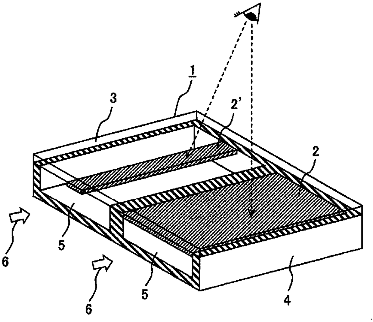
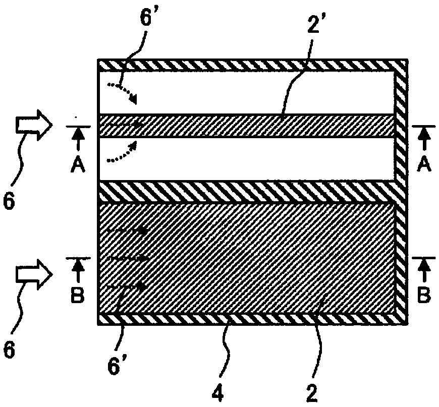
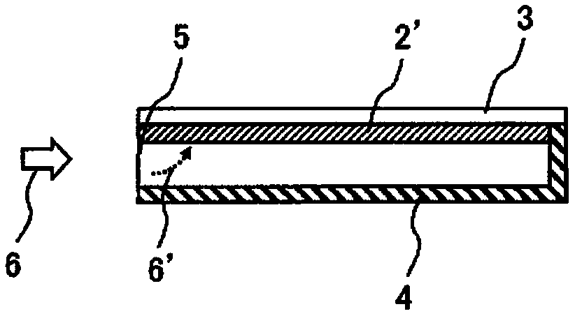
[0065] As mentioned above, since the structure and problems of the conventional corrosive environment monitoring apparatus were clarified, the structure of the corrosive environment monitoring apparatus of this invention is demonstrated below. exist Figure 1 to Figure 7 The configuration example and function of the corrosion environment monitoring device according to Embodiment 1 of the present invention are shown in . figure 1 It is a perspective view showing the overall configuration of the corrosion environment monitoring device according to Embodiment 1 of the present invention, figure 2 yes figure 1 top view of image 3 yes figure 2 A-A sectional view of the, Figure 4 yes figure 2 The B-B cross-sectional view. in addition Figure 5 , Image 6 , Figure 7 Respectively show the top view showing the corrosion situation of the metal thin film after the exposure of the corrosion environment monitoring device of Example 1, Figure 5 The A-A cross-sectional view o...
Embodiment 2
[0077] exist Figures 16-17 A configuration example of a corrosion environment monitoring device according to Embodiment 2 of the present invention is shown in FIG. Figure 16 is a stereogram, Figure 17 is a top view.
[0078] Will Figure 16 The corrosion environment monitoring device 1 related to the embodiment 2 of the present invention and figure 1 Compared with the corrosive environment monitoring device 1 of the embodiment 1, it is obvious that the design has multiple groups (in Figure 16 The metal thin films of the same configuration are common to the two groups in the middle, but the size of the channel structure 4 and the opening 5 which are the corrosion detection conditions in the corrosion environment monitoring part are set differently.
[0079] It demonstrates more concretely. In the corrosive environment monitoring device 1 , a sensor unit composed of two sets of metal thin films 2 attached on a transparent substrate 3 is disposed. The metal films 2 all ...
Embodiment 3
[0086] exist Figure 21 A configuration example of a corrosion environment monitoring device according to Embodiment 3 of the present invention is shown in . Figure 21 It is a form that uses the relationship of the wide and narrow metal thin films of Example 1 and the relationship of the high and low openings of Example 2 in combination.
[0087] Here, the combination of the channel structures with different heights of the openings and the metal thin films of different widths in Example 2 constitutes a sensing part having a channel with a narrow metal thin film attached to a high opening and a wide metal thin film attached to a channel with a high opening. The device of the sensing part of the channel of the low opening part.
[0088] Thus, a good linear relationship between the ratio of the length of the discoloration region and the corrosion thickness can be maintained, and by attaching a wide metal thin film to the sensing part of the channel with a low opening, the ASHRA...
PUM
| Property | Measurement | Unit |
|---|---|---|
| thickness | aaaaa | aaaaa |
Abstract
Description
Claims
Application Information
 - R&D
- Intellectual Property
- Life Sciences
- Materials
- Tech Scout
- Unparalleled Data Quality
- Higher Quality Content
- 60% Fewer Hallucinations
Browse by: Latest US Patents, China's latest patents, Technical Efficacy Thesaurus, Application Domain, Technology Topic, Popular Technical Reports.
© 2025 PatSnap. All rights reserved.Legal|Privacy policy|Modern Slavery Act Transparency Statement|Sitemap|About US| Contact US: help@patsnap.com


